Ultrasonic vs Radiographic Testing for Thick-Walled Welds
Choosing between ultrasonic testing and radiographic testing for a thick-walled weld is rarely a clean technology contest. The weld does not care which method has the better brochure.
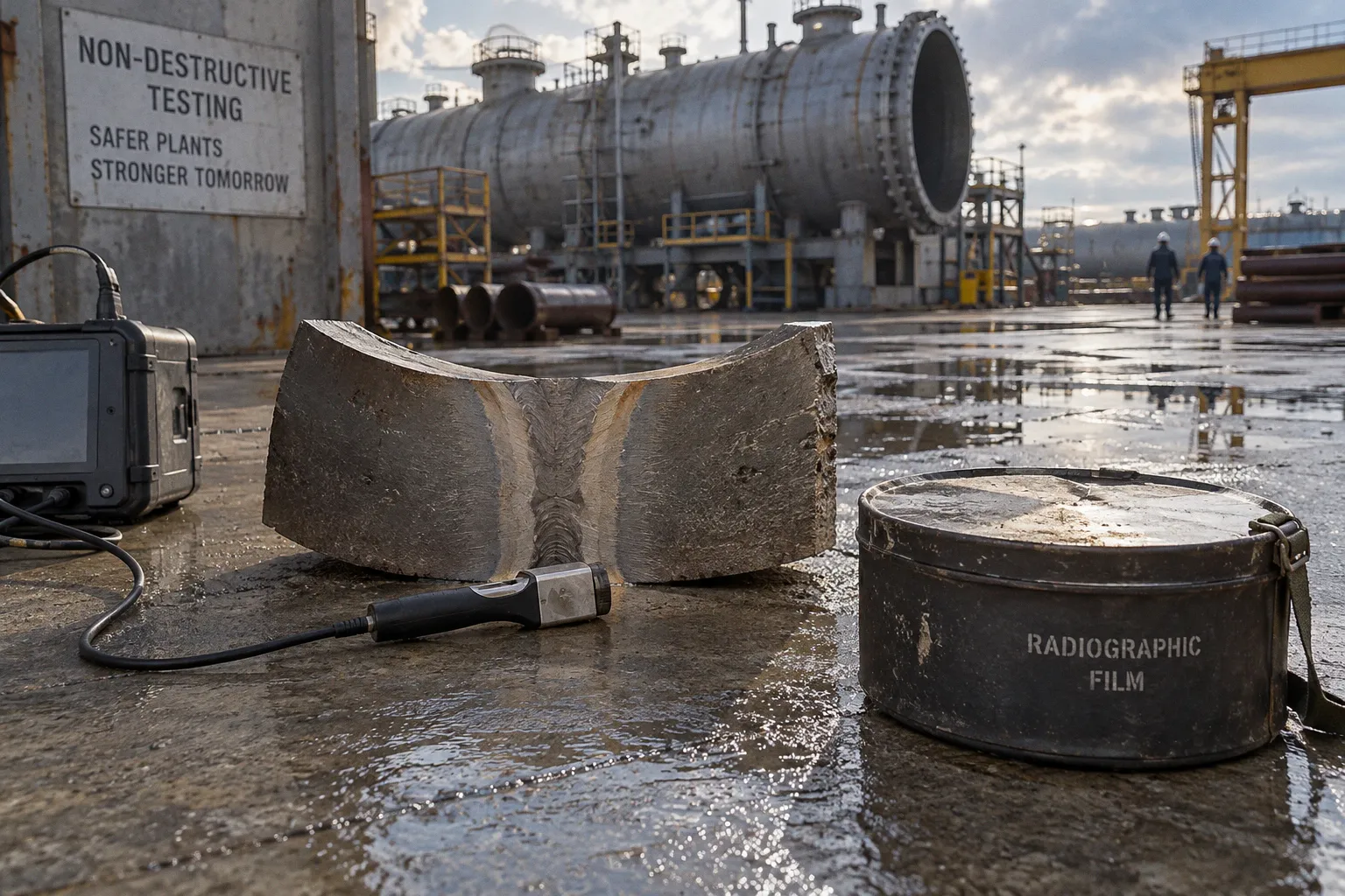
It cares whether the inspection can find the defect that actually threatens service, whether the result is traceable, and whether the method fits the governing code without turning production into a ceremonial queue.
That is the central problem with ultrasonic testing vs radiographic testing for thick-walled welds. UT and RT do not see the same things equally well. Ultrasonic testing is generally stronger against planar defects such as cracks and lack of fusion. Radiography is generally stronger against volumetric defects such as porosity and slag inclusions. Treating them as interchangeable tools is how quality plans become expensive and strangely optimistic.
The first question is not “UT or RT?” It is “What kind of defect are we trying to find?”
Both methods are volumetric non-destructive testing techniques, but “volumetric” does not mean “equally good at everything inside the weld.” Their physical principles create different strengths and blind spots.
Ultrasonic testing sends sound waves through the material and interprets reflections from interfaces or discontinuities. In weld inspection, standard equipment commonly operates in the range of 2.5 to 5 MHz. The inspector or automated system analyzes signal response, position and amplitude to estimate where a discontinuity sits and how large it may be.
Radiographic testing uses penetrating radiation to create an image of the weld volume. The result shows changes in material density and thickness along the radiation path. That makes RT particularly useful for defects that alter the volume of the weld in a relatively obvious way.
The practical division looks like this:
| Inspection concern | Ultrasonic testing | Radiographic testing |
|---|---|---|
| Cracks | Strong capability, especially for planar reflectors correctly oriented to the sound beam | Can miss tight or unfavorably oriented cracks |
| Lack of fusion | Generally strong when the discontinuity presents a suitable reflecting surface | Detection can be weaker, particularly when the defect is thin and planar |
| Porosity | Can detect it, but sensitivity depends on size, distribution and orientation | Typically strong because gas voids create visible density changes |
| Slag inclusions | Detectable, though interpretation can be complicated by geometry and morphology | Typically effective for volumetric inclusions |
| Defect depth | Usually provides useful depth positioning and sizing information | Image gives projection through the part; depth can be less direct |
| Permanent visual record | Digital data can be stored, but interpretation depends on system and procedure | Produces a radiographic image that is readily archived and reviewed |
| Radiation controls | No ionizing radiation exclusion zone | Requires controlled areas, dosimetry and radiation-safety management |
| Access | Often needs access to one side or a suitable scanning surface | Usually requires source and detector positioning around the weld |
| Operator dependence | High for manual UT; reduced with qualified automated systems | Strongly dependent on setup, exposure quality and interpretation |
This is not a table of winners. It is a map of failure modes. If the quality risk is lack of fusion at a sidewall, a method that is excellent at displaying rounded pores may still be the wrong first answer.
A weld inspection method is only “sensitive” to the defect it can physically see. The rest is marketing with a procedure number attached.
UT is usually the sharper tool for planar defects
Cracks and lack of fusion are planar discontinuities. Their danger comes not only from their presence but from their shape, orientation and position relative to the stress field. A narrow planar defect can be more structurally significant than a larger cluster of benign-looking rounded indications.
This is where ultrasonic testing often has the advantage. If the sound beam meets the defect at a useful angle, the interface can return a strong signal. The system can then provide information about location and depth that is valuable for acceptance decisions and repair planning.
A comparative evaluation of pressure-vessel weld defects found UT detection rates of 92% for cracks and 88% for lack of fusion. Radiographic testing detected cracks at 68% and lack of fusion at 55% in the same comparison. Those figures are not a universal performance guarantee. They describe comparative behavior under a particular evaluation, not a magic conversion chart for every alloy, thickness, weld profile or procedure. Still, the direction is hard to ignore.
Manual UT has a catch, naturally. The method depends on probe selection, scanning pattern, calibration, surface condition, weld geometry, operator skill and the orientation of the discontinuity. A poor angle can turn a serious reflector into a quiet screen. A rough cap or badly prepared scanning surface can complicate the result. Geometry can generate signals that resemble defects, while real defects can hide in regions where the beam is poorly aligned.
Modern phased array ultrasonic testing helps by using multiple elements and electronically controlled beam steering. Instead of relying on one fixed beam path, PAUT can examine a range of angles and generate a more informative data set. That improves coverage and supports imaging, sizing and review. It does not abolish the need for a qualified procedure. It simply gives the procedure better equipment to fail with if the setup is careless.
Time-of-flight diffraction, or TOFD, adds another approach to crack and planar-defect detection. It uses diffracted signals from the tips of a discontinuity to estimate its position and height. In heavy fabrication, TOFD and PAUT are often discussed together because they can provide complementary information: one method may be useful for detection and imaging, while the other strengthens sizing confidence.
The important phrase is automated or semi-automated equipment with computer-based data collection. Under the ASME provisions described in the available code framework, UT can substitute for RT in Sections I, VIII Division 1 and VIII Division 2 only under those conditions. Manual UT is not automatically accepted as a direct replacement for radiography simply because the technician is experienced or the instrument is modern.
That distinction belongs in the inspection plan before welding starts, not in the argument after a client asks why the required radiographs are missing.
RT still has a serious advantage with volumetric defects
Radiography is sometimes treated as an old technology waiting politely to be retired. That is too neat, and heavy steel is rarely neat.
For porosity and slag inclusions, RT remains highly effective because these discontinuities create density changes that can appear clearly in the radiographic image. In the cited comparative evaluation, RT detected porosity at 94%, compared with 61% for UT. For slag inclusions, RT reached 89%, while UT reached 65%.
Again, this does not make RT the universal winner. It shows why a weld full of volumetric contamination can be better served by radiographic inspection than by an ultrasonic method optimized for planar reflectors.
Radiography also offers a permanent visual record that is familiar to fabricators, inspectors, clients and auditors. A radiograph can be reviewed later, compared with other exposures and retained as part of the quality dossier. Digital radiography changes the medium, but not the basic attraction: the inspection leaves behind an image of the examined region rather than only an interpreted signal trace.
That record has practical value when acceptance is disputed. It also has limits. A radiographic image is a projection through the weld. It can show that an indication exists without making its exact depth immediately obvious. Overlapping geometry, exposure quality, sensitivity and defect orientation all affect interpretation. A small planar defect aligned with the radiation beam can be difficult to display, even when it matters mechanically.
Radiography is also not frictionless. It requires source and detector arrangement, exposure planning, controlled access and radiation-safety procedures. Industrial radiography operators in the United States must comply with requirements under 10 CFR Part 34 or equivalent Agreement State rules. These controls include area restrictions, dosimetry and the designation of a Radiation Safety Officer. Other jurisdictions use their own regulatory systems, but the operational principle remains: ionizing radiation creates a safety-management task that UT does not.
That task can interfere with production flow. Personnel may need to leave the area. Nearby work may stop. Exposure planning can become difficult in a crowded petrochemical fabrication environment. None of this makes RT technically weak. It makes RT operationally expensive when the worksite is busy, the component is large or the inspection must be repeated.
Code compliance is where informal comparisons go to die
Engineers often compare UT and RT as if the buyer can simply choose the more convenient one. Pressure-vessel and structural codes are less relaxed. They define what method is recognized, under which article, with what procedure, equipment and personnel qualification.
ASME Section V recognizes radiography under Article 2 and ultrasonic examination under Article 4 as volumetric examination methods. That establishes the methods within the code framework, but it does not mean every version of UT can replace every version of RT for every application.
For quality managers, the compliance question has several layers:
- Is the weld category covered by the applicable construction code?
- Does the code permit the selected examination method for this component and service?
- Is the procedure written for the actual material, geometry, weld type and thickness?
- Are the personnel qualified for the method and level of responsibility?
- Does the data collection system meet the requirements for an automated or semi-automated UT alternative?
- Are acceptance criteria defined before indications appear?
- Can the records demonstrate coverage, calibration and disposition?
This is less glamorous than debating which method is “more advanced.” It is also what survives an audit.
Why manual UT is not a shortcut around RT
Manual ultrasonic testing is attractive because it avoids radiation controls and can provide immediate feedback. It is also easy to oversell. A manual scan can be technically useful without being a code-compliant replacement for radiography.
The available ASME framework permits UT substitution for RT in specified sections when automated or semi-automated systems such as PAUT or TOFD are used with computer-based data collection. The requirement matters because automated acquisition improves repeatability, coverage documentation and reviewability. It creates a record of the scan rather than relying only on the inspector’s live interpretation.
That does not mean automated UT is independent of human judgment. The procedure still needs sensible probe positioning, calibration, scan plans, reference blocks or equivalent controls, and an interpretation process that understands the geometry. Automation makes the inspection more reproducible. It does not turn a bad scan plan into a good one.
A quality plan that says “UT instead of RT” without specifying the technology is not a modern plan. It is an unfinished sentence.
Detection probability is useful, but it is not a universal score
The phrase “probability of detection” sounds precise enough to settle the dispute. In practice, detection performance depends on more variables than a headline percentage can carry.
For UT, the result depends on:
- Sound velocity and attenuation in the material.
- Weld geometry and surface condition.
- Probe frequency and angle.
- Defect orientation relative to the beam.
- Calibration quality and reference reflectors.
- Access to the scanning surface.
- Manual or automated data collection.
- Inspector competence and interpretation discipline.
For RT, performance depends on:
- Radiation source energy and exposure arrangement.
- Material thickness and alloy characteristics.
- Film or detector response.
- Image quality and required sensitivity.
- Defect orientation in the projected image.
- Geometric unsharpness.
- Scatter control.
- Interpretation of overlapping indications.
The cited figures make the strategic contrast clear: UT performed better for cracks and lack of fusion, while RT performed better for porosity and slag. They do not justify saying that UT will find 92% of every crack in every thick-walled weld, or that RT will find 94% of every pore under production conditions. That would be false precision dressed as engineering.
A defensible inspection strategy therefore starts with the expected defect population. Consider the manufacturing route. Was the joint made with a process prone to slag entrapment? Is sidewall fusion the major concern? Are there known risks from high restraint, repair welding or hydrogen cracking? Does the component operate under cyclic loading where planar flaws deserve particular attention? Is the weld geometry likely to interfere with probe movement or image interpretation?
The answer is not always one method. A combined approach can be more rational than forcing a single inspection technology to cover every risk. UT may provide depth information and strong planar-defect sensitivity, while RT provides a useful record of volumetric quality. The additional examination must be justified by the risk and code requirements, not added as ritual because nobody wants to own the decision.
The cheapest inspection is not the one with the lowest invoice. It is the one that finds the dangerous defect before the component becomes a field problem.
Operational constraints matter more in petrochemical fabrication than brochures admit
A fabrication shop is not a laboratory. Welds are inspected among cranes, fit-up stations, blasting, coating, heat treatment, repairs and a schedule that has already been described as “tight” for six consecutive months.
UT fits well into many active production environments. It does not create an ionizing-radiation exclusion zone. It can often be performed with relatively rapid feedback, allowing repairs or additional examination decisions to happen without waiting for image processing. Automated UT can also produce data that supports later review and traceability.
But UT needs access. The scanning surface must be prepared well enough for reliable coupling and movement. Cladding, rough weld caps, attachments, limited access and complex geometry can restrict coverage. Thick or highly attenuative materials may reduce signal quality. The technique may require multiple probe positions, scanning directions or complementary methods to avoid orientation-related blind spots.
RT has different logistical problems. It may require the work area to be cleared and controlled. Nearby operations can be interrupted. The component must be positioned so the source and detector create a useful exposure. On large or thick sections, the exposure arrangement can become more demanding, although exact time and energy limits depend on the material, geometry and equipment.
Radiographic inspection also introduces a document-management advantage that should not be underestimated. A well-produced image is intuitive to many reviewers. UT data can be richer, but it is only useful if the file format, scan plan, calibration records and interpretation workflow are preserved. Digital data does not automatically equal usable data. A hard drive full of unlabeled scans is not a quality system; it is a future archaeological site.
The effect on repair cycles
Inspection method affects how quickly a repair can be evaluated. UT can often support a rapid examination after repair welding, provided the surface and temperature conditions are suitable and the procedure allows it. The inspector can identify the position of an indication and support targeted excavation.
RT produces a record that may be preferable for formal documentation, especially when the project specification is built around radiographic acceptance. But each exposure is a controlled operation, and repeated examinations can multiply disruption.
For a pressure vessel or petrochemical weld, the relevant question is not simply whether one scan is cheaper than one exposure. It is whether the entire inspection sequence reduces uncertainty:
1. Initial examination.
2. Indication interpretation.
3. Repair decision.
4. Excavation or weld removal.
5. Repair welding.
6. Re-examination.
7. Final record review.
8. Code and client acceptance.
A method that appears efficient at step one can become awkward by step six. Conversely, a more controlled initial examination may prevent repeated repairs by locating the defect accurately.
How to choose the method for a thick-walled weld
The selection should be tied to the failure risk, the code route and the real geometry—not to whichever inspection vendor has the newest presentation deck.
A practical decision sequence is:
1. Define the dominant defect risk.
If the concern is cracking or lack of fusion, UT deserves serious priority. If porosity and slag inclusions are the main concern, RT may offer stronger evidence.
2. Confirm the governing code and substitution rules.
Check whether the selected UT technique is accepted for the applicable ASME section and whether automated or semi-automated data collection is required. Do not treat manual UT as a universal replacement.
3. Review access and geometry before writing the procedure.
Identify scanning surfaces, weld caps, attachments, curvature, cladding and areas where the probe cannot travel. For RT, establish source-detector positions and exclusion-zone implications.
4. Match the data record to the decision.
If the project needs precise defect depth, sizing and location, UT may provide more useful information. If the project needs a permanent image of volumetric weld quality, RT may be more persuasive and easier to archive.
5. Build the safety and production controls into the plan.
Radiation safety is not a footnote. Neither is UT surface preparation, calibration or operator qualification. A method that cannot be deployed safely and consistently is not an effective method.
6. Decide whether complementary examination is justified.
Where the expected defects are mixed or the consequence of failure is high, combining methods may provide better coverage than arguing over a single winner.
This process is deliberately unexciting. That is a virtue. Good inspection planning is not supposed to produce a cinematic breakthrough. It is supposed to prevent a defect from becoming a pressure boundary incident.
The strategic answer: use the method that sees your risk, then prove it is compliant
For thick-walled welds, ultrasonic testing is often the stronger option for planar defects, particularly cracks and lack of fusion. Its ability to provide depth-related information and its freedom from radiation controls make it attractive in active fabrication environments. PAUT and TOFD can improve coverage, data collection and sizing when the procedure, equipment and personnel are properly qualified.
Radiographic testing remains highly valuable for volumetric defects. Its performance with porosity and slag inclusions, along with the permanent visual record, keeps it firmly relevant in pressure-vessel and petrochemical quality assurance. Its limitations are not evidence of obsolescence; they are reasons to avoid using it as the only answer to every defect type.
The sensible conclusion from the ultrasonic testing vs radiographic testing for thick-walled welds comparison is therefore not that one method has defeated the other. It is that the methods answer different questions.
Use UT when planar-defect sensitivity, depth location and production flexibility are central—and when the code permits the selected system. Use RT when volumetric-defect detection and image-based documentation carry more weight. Use both when the defect population, service risk or acceptance framework demands complementary evidence.
The blunt version is simpler: do not choose an inspection method because it is newer, cheaper or familiar. Choose it because it can find the defect that would actually matter, under a procedure the code will accept, with records that a competent reviewer can defend.