Local vs Furnace PWHT: Key Criteria for Weld Stress Relief
For thick steel welds, post-weld heat treatment is not simply a choice between two heating devices.
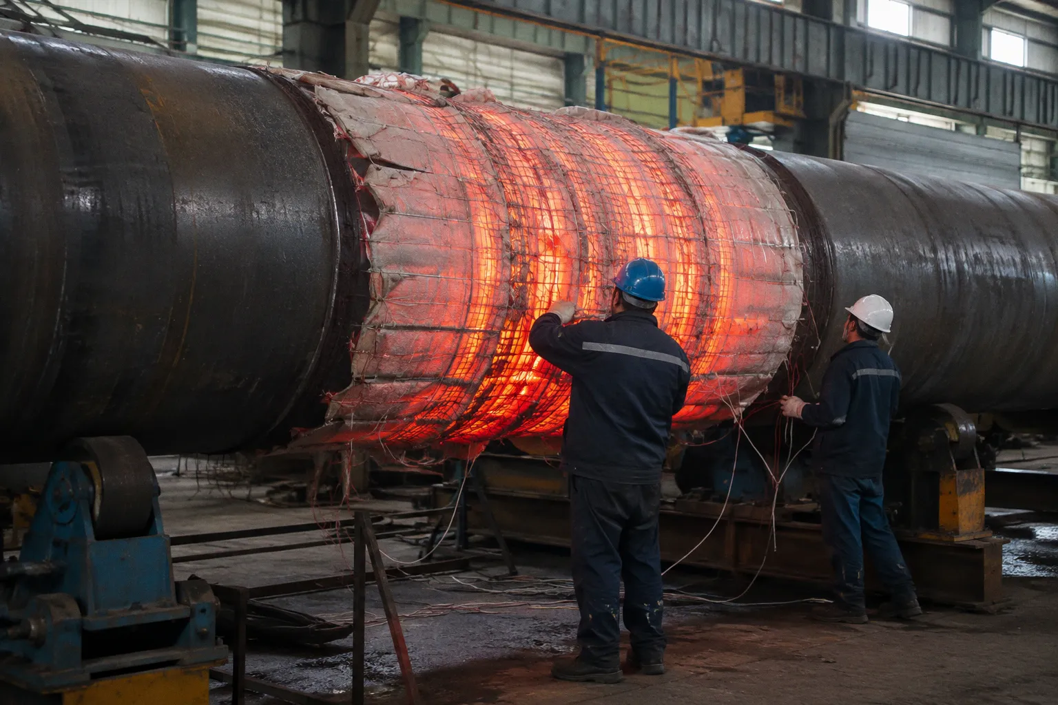
It is a decision about how the entire welded component will respond to temperature: through the wall, along the weld axis, and across adjacent regions affected by the heat cycle.
Furnace PWHT provides a relatively uniform thermal field around the component. Local PWHT applies heat to a defined band and must control the resulting axial and through-wall gradients. The distinction is mechanical, not cosmetic. A component can reach the required soak temperature at the weld while still developing unacceptable temperature differences elsewhere.
For carbon steel, the governing threshold may also change the decision before equipment availability is considered. ASME Section VIII Division 1 generally requires PWHT for carbon steel welds above a nominal thickness of 38 mm. ASME B31.3 uses a lower carbon-steel piping threshold of 19 mm. BS EN 13445 sets a 35 mm threshold for welded steel joints. Sour-service equipment introduces a different constraint: under NACE MR0175 / ISO 15156 requirements, PWHT is mandatory regardless of thickness.
The correct question is therefore not whether local or furnace PWHT is more convenient. It is whether the selected method produces a documented, controlled, and code-compliant thermal cycle for the actual geometry.
Regulatory Thresholds for Carbon Steel PWHT
PWHT is used to reduce welding residual stress and moderate the metallurgical and mechanical consequences of welding in thick sections. It does not remelt the weld metal. It does not reshape the external weld profile. It is a solid-state thermal process.
The first control point is the applicable construction code. The same material and nominal thickness can lead to different PWHT obligations depending on whether the component is a pressure vessel, process piping, or equipment designed to a European standard.
| Governing framework | Reference threshold or condition | Practical implication |
|---|---|---|
| ASME Section VIII Division 1, UCS-56 | Carbon steel welds above 38 mm nominal thickness | Furnace or local PWHT must be evaluated against pressure-vessel requirements |
| ASME B31.3 | Carbon steel piping welds above 19 mm nominal thickness | Piping systems can enter mandatory PWHT territory at a lower thickness |
| BS EN 13445 | Welded steel joints above 35 mm | European pressure-vessel fabrication may require treatment below the ASME VIII baseline |
| NACE MR0175 / ISO 15156 sour service | Mandatory regardless of thickness | Service environment can control the decision even when the wall is relatively thin |
These thresholds are starting points, not complete procedure specifications. Material grade, weld category, joint configuration, restraint, service conditions, and the exact design code can modify the final requirement. A threshold does not tell the fabricator how to heat the component. It tells the engineering team that the thermal cycle must be addressed.
This distinction matters in industrial steel structures and pressure-containing equipment. A general steel frame may not fall under the same PWHT provisions as a pressure vessel. A thick nozzle welded to a vessel may require a different treatment strategy from a long circumferential pipe weld. A large fabricated assembly may be impossible to place in a furnace even when furnace treatment would be thermally simpler.
The design record should identify at least four items before the PWHT method is selected:
- the governing construction code and applicable paragraph;
- the nominal thickness used for the code calculation;
- the material specification and weld procedure qualification;
- the service environment, including sour-service exposure where applicable.
Without these items, a comparison between local and furnace PWHT remains incomplete. The heating method is secondary to the acceptance basis.
The heating method is not the quality criterion. The controlled thermal history is.
Furnace Post-Weld Heat Treatment Criteria
Furnace PWHT surrounds the component with a controlled heat field. This is its primary advantage. The furnace reduces the risk that one side of a thick wall will lag significantly behind the other and makes it easier to maintain a stable soak temperature over the treated assembly.
For a component that fits inside the furnace, this method usually provides the most straightforward thermal condition. The entire pressure vessel, pipe spool, or fabricated section can be heated as one thermal system. Temperature recording is distributed through the load, and the furnace controls the general heating and cooling ramps.
Typical stress-relief soak temperatures for carbon steel fall in the range of 590–675 °C. The holding period is commonly based on a minimum of one hour per 25 mm of weld thickness. These values are not a substitute for the governing code or approved procedure. They describe the thermal logic of the treatment: reach the specified range, stabilize the component, hold long enough for the required stress-relieving response, and cool under controlled conditions.
The furnace method is particularly strong in the following conditions:
1. The component can be loaded without distortion risk.
Large or asymmetrical structures may sag when heated. Furnace treatment does not remove the need for supports, restraints, and load-positioning analysis.
2. The assembly has a relatively uniform wall thickness.
Uniform sections respond more predictably than structures combining heavy rings, thin shells, nozzles, base plates, and stiffeners.
3. The weldment requires treatment over a broad area.
If several welds are close together, treating the full assembly can avoid the thermal interaction problems created by multiple local heating zones.
4. Temperature measurement can represent the coldest and hottest locations.
A furnace display is not sufficient evidence that the weldment itself followed the required cycle. Thermocouple placement remains necessary.
5. The furnace capacity matches the actual geometry.
A component should not be forced into a furnace arrangement that creates blocked circulation, uneven exposure, or unsupported overhangs.
The common mistake is to treat furnace PWHT as automatically uniform. The furnace provides a more uniform environment. It does not guarantee uniform component temperature at every moment. Thick walls, abrupt changes in section, attachments, and restricted furnace circulation can still create thermal differences.
ASME furnace rules include limits on temperature differentials across the component during soaking. A commonly cited maximum differential is 150 °F, or approximately 83 °C, under the relevant furnace conditions. The limit exists because the component can carry significant thermal stress even after the furnace atmosphere appears stable.
Heating rate also requires control. A standard guideline used in this context limits the maximum heating rate to 400 °F per hour divided by the component thickness, with the thickness expressed in inches. The calculation is not a decorative entry on a chart. It defines how quickly the outer region is permitted to move toward the soak range while the interior is still colder.
For thick steel, the interior has a slower thermal response. If the surface temperature rises too quickly, the surface expands while the core resists that expansion. During cooling, the direction of the thermal imbalance reverses. These transients affect the residual stress field and can introduce distortion, especially in restrained or geometrically discontinuous assemblies.
Thermal Gradient Management in Localized Heating
Local PWHT is used when the complete component cannot be placed in a furnace or when treating only a defined weld region is more practical. Heating may be applied with ceramic resistance pads, induction equipment, or another controlled local system. The weld and surrounding band are brought into the required temperature range while the remaining structure stays outside the primary heating zone.
The method is technically valid. It is not thermally simple.
A localized heating band creates a temperature field that changes in at least three directions:
- through the wall thickness;
- along the weld axis;
- from the heated band into the colder parent metal.
The result is a non-linear thermal gradient. The weld may be at the target soak temperature while the adjacent material is substantially cooler. The inner surface may lag behind the outer surface. The ends of the heated band may develop steep axial gradients. Each condition affects thermal expansion and contraction.
This is why local PWHT cannot be evaluated by asking only whether the weld reached 600 °C, or another specified temperature. The relevant question is whether the entire controlled zone followed the required temperature profile and whether the gradient remained within the applicable requirements.
WRC 452 is commonly used as a reference for managing local heat treatment conditions in pressure-containing components. Its relevance is the relationship between the heated region and the surrounding colder metal. The procedure must define the band width, the placement of heaters, the insulation arrangement, the temperature-monitoring system, and the permitted gradients.
The localized PWHT soak band width is therefore a design parameter. It should not be selected from a generic rule without considering:
- wall thickness;
- pipe or shell diameter;
- weld type and orientation;
- nozzle or attachment geometry;
- proximity of other welds;
- material response;
- restraint and support conditions;
- access to both sides of the component.
A narrow band can create an abrupt thermal transition. A wider band distributes the temperature change over a greater distance, but it also increases the heated mass, power demand, and control burden. The correct width is the result of the applicable standard and engineering assessment, not a visual estimate made at the worksite.
Through-wall temperature control
Thick steel sections are vulnerable to through-wall differentials because heat must travel from the heated surface toward the opposite surface. If the outer surface is controlled directly and the inner surface is not monitored, the recorded temperature may not describe the most important part of the component.
For a shell or pipe, thermocouples may be required on both sides or at locations selected to demonstrate that the temperature distribution remains acceptable. The arrangement depends on access and code requirements. Where internal access is unavailable, the procedure must compensate through engineering analysis, validated heating arrangements, or other documented controls.
The thermal lag is not constant. It changes during heating, soaking, and cooling. A surface can reach the target range before the wall has stabilized. The nominal soak clock should not be treated as proof that the entire thickness has experienced the same thermal exposure.
Axial temperature control
The ends of a local heating band are high-risk regions. The weld is hot. The surrounding parent metal is cooler. The transition between the two can generate axial thermal stress. If the band is too narrow, the gradient becomes sharper. If the component is highly restrained, the expansion has fewer ways to occur without loading the weldment.
Insulation is part of the thermal design. It reduces heat loss and softens the transition into the colder material. Poor insulation can produce an asymmetric heat field, particularly around supports, attachments, penetrations, or areas exposed to air movement.
Local PWHT also requires a stable relationship between heater output and measured temperature. A thermocouple reading from one point cannot represent the entire band if the heating pattern is uneven. Multiple control and recording channels are often necessary to identify hot spots, cold spots, and lagging regions.
Soak Time and Ramp Rate Dynamics in Thick-Walled Welds
The soak period receives most of the attention because it is easy to specify: a temperature range and a minimum holding time. In thick-walled welds, the heating and cooling ramps can be equally important.
Research and simulation work indicates that much of the stress-relieving creep strain accumulates during the heating and cooling ramps rather than exclusively during the hold at soak temperature. This changes the practical meaning of ramp-rate control. The ramp is not merely the period before the real treatment begins. It is part of the stress-relief mechanism.
The heating cycle must therefore be read as a sequence of mechanical states:
1. Initial heating creates differential expansion.
The heated surface expands first. The colder interior and adjacent material resist that movement.
2. The thermal field penetrates the wall.
The temperature difference through the section changes. The location and magnitude of thermal stress also change.
3. The component approaches the soak range.
The heating rate determines how quickly the assembly transitions into a state where stress-relieving creep can occur.
4. The soak period stabilizes the required exposure.
The weldment remains within the specified temperature range for the required time based on the applicable code and procedure.
5. Cooling reverses the thermal sequence.
Surface contraction begins before the interior has cooled. The cooling rate and insulation determine how sharply the gradient develops.
The usual rule of one hour per 25 mm is a minimum holding-time framework, not a universal answer for every geometry. The controlling thickness must be defined correctly. Weld thickness, nominal wall thickness, and the thickness used by the construction code are not always interchangeable.
The heating-rate guideline of 400 °F per hour divided by thickness is also applied within a specific code framework. It should be converted consistently and correlated with the actual component geometry. A thick cylindrical shell and a flat restrained plate may require different practical controls even if their nominal thickness is identical.
Local PWHT places greater pressure on the ramp-control system because the heated zone is continuously exchanging heat with the surrounding structure. Furnace treatment tends to reduce this exchange by heating the whole assembly. Local treatment must manage it directly through heater zoning, insulation, power modulation, and thermocouple feedback.
A temperature chart should therefore show more than a successful endpoint. It should make the thermal cycle legible:
- heating rate;
- temperature spread across monitored points;
- arrival at the soak range;
- stabilization before timing begins;
- soak duration;
- cooling rate;
- temperature differential during cooling;
- any interruption, power loss, or sensor failure.
If the chart contains only one temperature channel from the hottest location, it may document the heater rather than the component.
A compliant soak temperature reached by one sensor is not the same as a compliant thermal cycle across a thick weldment.
Local and Furnace PWHT: Where Each Method Holds Its Advantage
The comparison becomes clearer when the methods are evaluated against the same engineering variables.
| Parameter | Furnace PWHT | Local PWHT |
|---|---|---|
| Thermal uniformity | Generally more uniform across the component, subject to load arrangement and furnace circulation | Depends on band width, insulation, heater zoning, and temperature-gradient control |
| Component size | Limited by furnace dimensions and load capacity | Suitable for large vessels, pipelines, and structures that cannot be moved |
| Control of adjacent welds | Can treat multiple welds and the surrounding assembly together | Requires assessment of thermal interaction between neighboring welds |
| Through-wall heating | Usually easier to achieve uniformly | Requires deliberate control and monitoring of surface-to-surface temperature differences |
| Axial gradient | Lower risk when the whole component is heated | Central design issue at the ends of the local heating band |
| Distortion risk | Still present, especially in asymmetrical assemblies and poorly supported loads | Can be significant if heating is uneven or restraint is high |
| Instrumentation | Distributed thermocouples and furnace control system | More intensive local monitoring, heater zoning, and recording |
| Site access | Requires transport to a suitable furnace | Can be performed at the fabrication site or installation location |
| Engineering documentation | Focuses on furnace qualification, load arrangement, supports, and cycle records | Requires detailed thermal layout, band definition, gradient limits, and local procedure control |
| Best technical fit | Components that fit safely and can be heated as a stable assembly | Large or immovable components where local thermal control can be demonstrated |
This table does not establish a universal ranking. Furnace PWHT is not automatically superior, and local PWHT is not merely a compromise. The methods solve different physical constraints.
Furnace treatment is often the lower-complexity option when the component fits and can be supported correctly. It reduces the number of local thermal transitions and usually simplifies temperature equalization. Its limitations are logistical and geometric.
Local treatment is often the only realistic option for a large pressure vessel, installed piping, or heavy fabricated structure. Its limitation is the greater sensitivity to gradients. The procedure must prove that the heated zone is wide enough, that the opposite surface is controlled, and that the adjacent cold material does not impose an unacceptable thermal discontinuity.
The decision should also account for weld distribution. A component with one isolated circumferential weld may be a manageable candidate for local PWHT. A component with several closely spaced nozzles, reinforcing pads, and longitudinal seams may produce overlapping thermal fields that are difficult to control. In that case, treating a larger section—or using a furnace—may provide a more stable thermal condition.
NACE Compliance and Stress Corrosion Cracking Prevention
Sour service changes the decision structure. Equipment designed for environments covered by NACE MR0175 / ISO 15156 requires PWHT regardless of thickness. The reason is service exposure, not simply the dimensional threshold used for ordinary carbon-steel fabrication.
Hydrogen sulfide environments increase the concern for sulfide stress cracking and related forms of stress corrosion damage. Residual tensile stress in a welded component becomes a service-relevant variable. A thin component is not exempt merely because it falls below a general thickness threshold.
This does not mean that any PWHT method will automatically satisfy sour-service requirements. The procedure still needs to demonstrate control of the thermal cycle and compatibility with the material and weld procedure. Local treatment requires particular discipline because the remaining cold structure can preserve or redistribute stress if the thermal field is poorly designed.
For sour-service equipment, the engineering record should connect the following elements:
- material and hardness control;
- welding procedure qualification;
- PWHT applicability;
- heating and cooling rates;
- temperature measurement;
- thermal-gradient limits;
- inspection and acceptance criteria;
- traceability of the treated weld.
PWHT is one control in a larger integrity system. It should not be presented as a single corrective operation that eliminates every cracking mechanism. It addresses residual stress through a specified thermal cycle. It does not replace appropriate material selection, welding control, hardness verification, or non-destructive examination.
Engineering Limitations of Localized Stress Relief
The main limitation of local PWHT is not the ability to heat steel. Industrial heaters can reach the required temperature range. The limitation is proving that the component experienced the intended thermal field.
A local procedure becomes weak when it relies on assumptions that are not measured or engineered. Common examples include:
- defining the band by heater dimensions alone;
- placing thermocouples only on the heated surface;
- using one controller for a geometrically complex weld;
- ignoring attachments and nearby welds;
- allowing uncontrolled air cooling at the band edge;
- starting the soak timer before the section has stabilized;
- treating the maximum temperature as more important than the temperature differential;
- accepting a chart with missing channels or unexplained interruptions.
These are not administrative defects. They can change the stress state of the weldment.
Local geometry matters
A cylindrical shell, a forged nozzle, a pipe elbow, and a flat plate do not distribute heat in the same way. Curvature changes the contact between heater and component. Nozzles create three-dimensional heat flow. Reinforcing pads act as thermal masses. Stiffeners can draw heat away from the band or restrict expansion.
The closer the geometry is to a simple, uniform shell, the easier it is to predict. The more discontinuities present, the stronger the case for a thermal analysis or a validated procedure tailored to the component.
Restraint matters
PWHT is performed on a component that is often heavy, supported, and partially restrained. Supports can prevent free thermal expansion. Temporary fixtures can create local stress concentrations. Welded attachments can pull against the heated band.
The component must be allowed to respond to temperature within controlled limits. This may require an explicit support arrangement, not merely placing the assembly on whatever stands are available. The support strategy belongs in the procedure because it affects the thermal and mechanical response.
Local PWHT does not guarantee furnace-equivalent results
Local PWHT can reduce residual stress effectively when the thermal cycle and gradient controls are appropriate. It should not be described as producing identical absolute stress reduction to full-furnace treatment without specific engineering simulation or thermal-gradient verification under the relevant guidance.
The difference is fundamental. Furnace PWHT exposes the broader component to a common thermal history. Local PWHT creates a treated region within a larger structure that follows a different temperature path. The two methods may both satisfy the applicable requirements, but they do not generate the same thermal field by default.
For non-standard wall geometries, the exact residual stress reduction from local treatment cannot be assumed without analysis. Finite-element modeling, thermal measurement, procedure qualification, or a combination of these may be necessary where the geometry or service consequence justifies it.
Inspection After PWHT
PWHT does not replace inspection. It changes the condition of the weldment and should be integrated into the inspection sequence defined by the fabrication specification.
The relevant inspection plan may include radiographic testing, ultrasonic testing, surface examination, dimensional checks, and hardness or material verification where required. The selected method depends on the weld type, thickness, material, code, and service.
Ultrasonic testing is sensitive to geometry, access, calibration, and operator technique. Radiographic testing provides a different view of volumetric discontinuities. Neither method should be treated as a universal substitute for the other. The inspection plan should identify what defect types must be detected and which method is technically capable of finding them.
Dimensional inspection is also relevant after thermal treatment. Large assemblies can move during heating and cooling. A weld may meet the thermal requirements while the component develops unacceptable distortion or alignment error. For precision industrial equipment and structural assemblies, three-dimensional laser scanning can document the post-treatment geometry more effectively than isolated manual measurements.
The inspection record should preserve traceability between:
- weld identification;
- material heat and joint records;
- approved welding procedure;
- PWHT procedure;
- thermocouple layout;
- time-temperature chart;
- non-destructive examination results;
- dimensional condition after treatment.
A detached temperature chart is weak evidence. The chart must be tied to the weld and component that were actually treated.
A Practical Selection Sequence
The local-versus-furnace decision can be made with a short engineering sequence, provided each step is documented rather than handled as a verbal preference.
1. Establish the governing code.
Identify whether the component is controlled by ASME Section VIII, ASME B31.3, BS EN 13445, or another specified standard. Do not combine thresholds from different codes without confirming their applicability.
2. Confirm whether PWHT is mandatory.
Review nominal thickness, material group, weld type, service conditions, and sour-service requirements. Under NACE MR0175 / ISO 15156 conditions, thickness does not remove the PWHT requirement.
3. Map the geometry.
Record wall thickness changes, diameter, weld orientation, nozzles, pads, stiffeners, supports, and nearby welds. Local heating decisions made without a geometric map are incomplete.
4. Test furnace feasibility.
Check furnace dimensions, load capacity, circulation, support arrangement, heating uniformity, and the possibility of distortion. Physical fit is not enough.
5. Define the local thermal field if furnace treatment is impractical.
Establish the heated band, insulation, heater zoning, thermocouple locations, control channels, and allowable gradients in accordance with the applicable requirements.
6. Control the complete cycle.
Record heating rate, stabilization, soak, cooling rate, and temperature differentials. The record should show the component’s response, not only the controller setpoint.
7. Verify the treated condition.
Complete the required non-destructive examination, dimensional inspection, and any additional testing specified for the material or service.
8. Review deviations before acceptance.
A power interruption, sensor failure, temperature excursion, or unexplained chart gap requires engineering disposition. It should not be hidden by renaming the cycle or restarting the clock without assessment.
This sequence is deliberately mechanical. It prevents the decision from being reduced to cost or convenience before the thermal problem has been defined.
The Decision in One Sentence
Choose furnace PWHT when the component can be heated as a stable, representative assembly with acceptable support and uniformity. Choose local PWHT when the component cannot be moved or fully heated, but only after the localized band and thermal gradients have been engineered, monitored, and documented.
For thick steel welds, the decisive variable is not the heater type. It is temperature distribution over time. Furnace treatment generally reduces the complexity of that distribution. Local treatment transfers the complexity into band design, insulation, instrumentation, and gradient control.
The final record should make five points unmistakable:
- the applicable code and PWHT obligation;
- the reason the selected method fits the component;
- the thermal limits governing the cycle;
- the evidence that the weldment followed those limits;
- the inspection results confirming the post-treatment condition.
When those points are present, local and furnace PWHT can both be defensible stress-relief methods. When they are absent, a successful temperature reading proves very little.