Tube-to-Tubesheet Joints: When to Weld vs Expand Tubes
A shell-and-tube heat exchanger can be correctly designed, correctly fabricated, and still develop a leak at its most concentrated interface — the small joint where each tube enters the tubesheet.
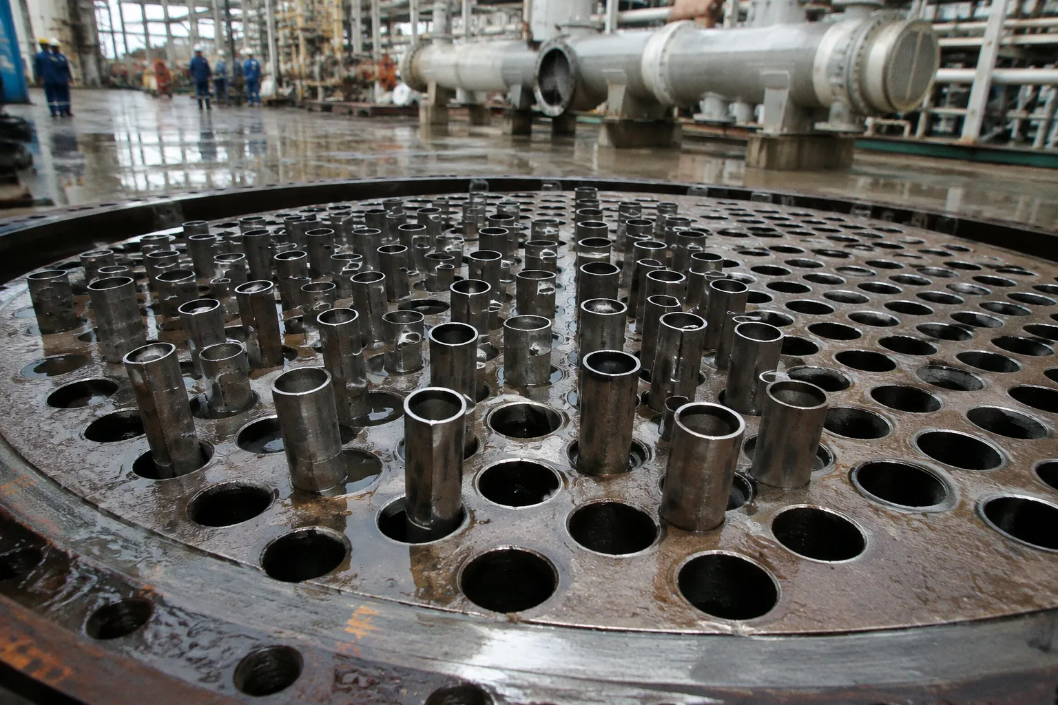
The choice between mechanical expansion, welding, or a combined joint is therefore not a finishing detail. It is a decision about how the exchanger will contain pressure, tolerate temperature change, and keep process fluid separated from the shell-side medium over time.
For low-severity service, tube expansion can provide a sound mechanical joint without adding a weld to every tube. As pressure, temperature, thermal cycling, corrosion risk, or fluid hazard increases, the joint usually needs a metallurgical barrier as well — a seal or strength weld, sometimes followed by controlled expansion. The right answer in heat exchanger tube to tubesheet joint selection is rarely simply “weld” or “expand.” It is a sequence built around the service conditions and the behavior of the two materials.
Expansion creates holding force through controlled deformation; welding creates continuity through fused metal. The joint should be chosen according to which kind of failure the service is most likely to provoke.
Mechanical expansion: where the simpler joint remains the right one
Mechanical expansion, often called tube rolling or tube expanding, locks the tube into the tubesheet by plastically deforming the tube wall against the drilled hole. The tube is not fused to the tubesheet. Its resistance comes from contact pressure, friction, and the geometry created during rolling.
That mechanism is dependable when the service is comparatively gentle. Pure expansion is generally suited to design pressure up to 4 MPa and design temperature up to 300 °C, provided the exchanger is not exposed to severe thermal cycling or stress-corrosion conditions. These limits should not be read as a universal permission slip: fluid chemistry, differential thermal expansion, tube vibration, material pairing, and the consequences of leakage still shape the final decision. But they establish a useful boundary. Below this level, mechanical expansion can be efficient and technically sufficient; above it, the margin for relying on friction alone becomes much narrower.
A properly expanded joint must achieve several things at once:
- create enough radial contact pressure to resist tube pullout;
- seal the process side against leakage;
- avoid excessive thinning or buckling of the tube wall;
- remain stable after fabrication and during operation;
- avoid damaging the tubesheet hole or creating sharp local stress concentrations.
The rolling operation is therefore not just a matter of inserting a tool and turning it until the tube feels tight. The reduction in tube wall must be controlled, and the tool must work over the specified joint length. Excessive rolling can thin the tube, distort the hole, or leave residual stresses that become significant when the exchanger sees temperature changes. Insufficient rolling may leave an apparently neat tube end with inadequate holding force.
TEMA rules provide a geometric baseline: the tube should be expanded for a length of at least 2 inches, or 50 mm, or for the tubesheet thickness minus 1/8 inch, or 3.2 mm, whichever is smaller. The expansion should not extend beyond the shell-side face of the tubesheet. That last point is practical as much as dimensional. Extending the expanded zone too far can interfere with the intended stress distribution and may create an undesirable condition at the shell-side surface.
In a conventional exchanger with moderate pressure, moderate temperature, compatible metallurgy, and no severe cyclic duty, this joint can be the cleanest solution. It avoids weld defects at the tube end, reduces heat input, and can simplify production. It also keeps the joint mechanically direct — tube against tubesheet, with the quality of the result depending on material behavior and process control rather than on a small weld bead repeated hundreds or thousands of times.
When expansion alone no longer gives enough protection
The first question in tube expansion vs strength welding is not which method is faster. It is what happens if the joint begins to leak.
A small leak may be tolerable in one service and unacceptable in another. If the process fluid is toxic, flammable, highly corrosive, or otherwise hazardous, the tubesheet joint becomes a containment boundary whose reliability deserves a higher level of protection. The same is true when a leak could contaminate a valuable product, damage downstream equipment, or force an entire exchanger train out of service.
At elevated pressure and temperature, the joint is also exposed to stronger mechanical and thermal demands. The tube and tubesheet may expand at different rates. Repeated starts and shutdowns can work against the contact pressure created during rolling. A joint that is stable under steady conditions may be less comfortable under a cycle of heating, cooling, pressurization, and depressurization.
In such cases, welding supplies a fused metallic connection. A properly designed weld can provide a leak-tight metallurgical bond and, depending on the joint design and governing requirements, contribute structural strength as well. This is why welded joints are generally preferred for high-pressure or high-temperature service, particularly where thermal cycling, stress corrosion, or hazardous fluid duty raises the cost of even a small loss of containment.
The phrase “strength welding” should not be used loosely. A seal weld and a strength weld do not necessarily carry the same design responsibility, and the required joint configuration must come from the exchanger design, applicable code, material specification, and inspection plan. The practical distinction is clear, however:
- a seal weld is primarily intended to close the leakage path;
- a strength weld is designed to contribute to the mechanical integrity of the tube-to-tubesheet connection;
- a welded-and-expanded joint combines a metallurgical barrier with mechanical contact and holding force.
The combined arrangement is often selected when leakage prevention and mechanical restraint both matter. Expansion can close small clearances and stabilize the tube within the hole, while the weld provides the primary leak-tight barrier. But the order of operations matters. If post-weld heat treatment is specified, tube expansion must be performed after PWHT. Expanding first can alter the joint condition before heat treatment, while the subsequent thermal cycle may change stresses and dimensions that the expansion operation was intended to control.
This is one of those details that can disappear inside a fabrication schedule and then return later as a quality problem. The joint is not defined only by the final appearance at the tubesheet face. It is defined by the metallurgy, sequence, heat input, expansion condition, and inspection results that produced that appearance.
The wall reduction percentage is a process window, not a decorative number
For a mechanically expanded tube, the critical quantity is not simply how far the tube has been rolled. It is the degree to which the tube wall has been reduced in the expanded zone. The target must be high enough to create reliable contact and low enough to preserve the tube’s integrity.
The available ranges vary by metallurgy:
| Tube material | Typical target wall reduction | Stated maximum where provided |
|---|---|---|
| Carbon steel and low-alloy steel | 5–8% | 8% under API 660 |
| Austenitic stainless steel | 5–8% | 6% under API 660 |
| Duplex stainless steel | 2–6% | Not specified in the available data |
| Titanium | 4–6% | 5% under API 660 |
| Copper and copper alloys | 7–10% | 8% under API 660 |
These figures are not interchangeable across materials. A percentage that is reasonable for copper or a copper alloy may be excessive for austenitic stainless steel under a particular specification. Duplex stainless steel may require a narrower, more conservative process window because its deformation response and work-hardening behavior differ from those of ordinary austenitic grades.
The target also needs to be connected to actual production control. A rolling program should account for tube outside diameter, wall thickness, tubesheet hole diameter, tube and tubesheet hardness, lubricant condition, tool calibration, and the length of the expanded zone. The same nominal rolling setting will not necessarily produce the same result across different lots of material or different tube bundles.
A reliable production approach settles the following before the bundle reaches final assembly:
1. The material pair and hardness relationship — not just the grade names, but how the tube and tubesheet respond to deformation.
2. The specified reduction range — with a defined target, not merely a broad allowable limit.
3. The measurement method — so that operators and inspectors are evaluating the same physical feature.
4. The rolling sequence — especially where welding or PWHT is part of the joint design.
5. The acceptance criteria — including leakage testing and examination appropriate to the service.
This is where tubesheet joint leak prevention becomes less about choosing an attractive process and more about keeping the process repeatable. A mechanically expanded joint can be very reliable when the rolling operation is treated as a controlled forming process. It becomes vulnerable when the operator is asked to compensate by feel for variations that should have been resolved in engineering and procedure qualification.
Metallurgical compatibility decides whether expansion can work
The tube and tubesheet do not need to be identical materials, but their mechanical relationship must support the joint. During expansion, the tube must deform against the tubesheet hole in a way that creates locking force rather than simply pushing the softer component out of shape.
A tube made from a harder material than the tubesheet should not be expanded into that softer tubesheet. In that situation, the tubesheet may deform excessively while the tube fails to create the intended mechanical lock. The result can look like a completed joint while lacking the contact pressure and stability required for service.
That is a quiet failure mode — no dramatic weld crack, no obvious missing component, just a joint whose basic mechanics were mismatched from the beginning.
Material pairing also affects welding. Dissimilar alloys can introduce differences in thermal expansion, dilution, corrosion resistance, and weldability. The weld procedure must control heat input and filler selection in a way that preserves the required properties at the joint. If the exchanger operates with aggressive fluids or large temperature differences, a connection that is sound in the workshop may still need careful assessment for thermal fatigue and corrosion-assisted degradation.
For this reason, the tube-to-tubesheet seal weld criteria should be connected to the whole exchanger rather than treated as a local welding question. The design team needs to know:
- which side of the joint is exposed to the process fluid;
- whether the weld is a seal weld or carries structural load;
- what pressure and temperature the connection must contain;
- whether the service includes thermal cycling or vibration;
- whether the materials are compatible for expansion, welding, and corrosion resistance;
- whether PWHT is required and how it changes the fabrication sequence.
A tubesheet is not just a thick plate with many holes. It is the place where shell-side pressure, tube-side pressure, tube loads, thermal movement, drilling accuracy, and weld or expansion stresses converge. The joint method must settle into that larger mechanical picture.
The strongest-looking joint is not automatically the safest one. Compatibility, sequence, and service conditions decide whether strength remains strength after the exchanger begins to breathe through its operating cycles.
TEMA geometry and fabrication sequence belong in the same conversation
The geometry of the tubesheet hole controls how much useful contact can be created, where the expanded zone sits, and how the tube end relates to the shell-side face. Hole condition matters as well. Burrs, scratches, poor surface finish, or dimensional variation can turn a theoretically sound expansion into an inconsistent row of joints.
For a welded connection, the tube projection and preparation at the tubesheet face become equally important. The weld must have enough access and repeatability to form the intended profile without excessive heat input or irregular penetration. In a large shell-and-tube heat exchanger assembly, hundreds or thousands of small variations accumulate. One imperfect tube end may not be visible in a general inspection, yet it can become the path through which cross-contamination begins.
A stable sequence often follows this logic:
- prepare and inspect the tubesheet holes;
- confirm tube material, dimensions, and surface condition;
- insert and position the tubes with the specified projection;
- carry out welding where the design requires it;
- complete PWHT when specified;
- perform expansion after PWHT for welded-and-expanded joints;
- verify the expanded condition and weld quality;
- conduct the required leak or pressure testing.
The exact procedure belongs to the project specification and governing code, but the principle is consistent: the operation that changes the final mechanical condition of the joint should not be performed prematurely. Expansion before a required PWHT is a clear example. The sequence is not a clerical preference; it protects the relationship between deformation, heat treatment, and final sealing.
Inspection should follow the joint’s actual failure modes. Visual examination alone cannot demonstrate the full quality of an expanded joint, and a visually continuous weld does not by itself prove leak-tightness under service conditions. The selected tests should be capable of finding the defects that matter for the exchanger — leakage paths, incomplete fusion, unacceptable geometry, tube damage, or inadequate expansion.
This is also why a generic choice between “automatic welding” and “hydraulic expansion” is too narrow. The method must be matched to bundle size, tube material, access, required repeatability, inspection capability, and the consequences of rework. There is no universal cost multiplier that makes one process the winner for every exchanger. The fabrication economy emerges from the complete chain — preparation, production rate, qualification, inspection, repair, and the value of avoiding a leak after commissioning.
A practical decision path for joint selection
When the design team is deciding between expansion, welding, or a combined joint, the following sequence keeps the decision anchored to the equipment rather than to workshop habit.
1. Start with design pressure and temperature.
If the service is above approximately 4 MPa or 300 °C, pure expansion should not be treated as the default. The duty may require welding or a welded-and-expanded arrangement, with the final decision confirmed by the governing design basis.
2. Ask how severe the operating cycle is.
Repeated thermal cycling, frequent starts and shutdowns, or meaningful differential expansion between tube and tubesheet can erode the margin of a friction-based joint.
3. Classify the consequence of leakage.
Hazardous fluids, product contamination, environmental exposure, and difficult access for repair all favor a more robust leak-tight strategy.
4. Match the material behavior.
Confirm that the tube can deform properly into the tubesheet. A harder tube should not be expanded into a softer tubesheet. For welded joints, confirm weldability, filler compatibility, corrosion resistance, and heat-treatment requirements.
5. Define the joint’s actual function.
Is it intended to resist pullout, prevent leakage, carry structural load, or do all three? The answer separates a simple expanded joint from a seal-welded or strength-welded design.
6. Fix the geometry and process window.
Establish the expansion length, wall reduction target, tube projection, weld preparation, and inspection method before fabrication begins.
7. Place PWHT in the correct sequence.
For welded-and-expanded joints requiring PWHT, complete heat treatment before expansion. The final expansion operation should reflect the post-PWHT condition of the assembly.
The result may be different from one exchanger to the next, even when the equipment looks similar from the outside. A moderate-pressure cooler with compatible materials and stable operation may be well served by controlled expansion. A high-temperature exchanger handling hazardous process fluid may need a welded joint. A severe duty with demanding leakage requirements may justify the additional control of welding plus expansion.
The answer is usually visible in the service conditions
Mechanical expansion remains a valuable and efficient joint method when its operating envelope is respected. It can provide reliable tube retention and sealing without introducing repeated weld heat input into the tubesheet. But its reliability depends on correct deformation, adequate joint length, compatible metallurgy, and a service that does not ask the contact joint to tolerate more than it was designed to bear.
Welding becomes the stronger candidate when pressure, temperature, thermal cycling, stress corrosion, or fluid hazard makes leakage unacceptable. A combined welded-and-expanded joint can add another layer of control, provided the design distinguishes the role of each part and the fabrication sequence is protected — especially where PWHT is involved.
So the practical answer to heat exchanger tube to tubesheet joint selection is this: expand when a controlled mechanical lock is sufficient for the duty; weld when containment and service severity demand metallurgical continuity; combine both when the exchanger needs the advantages of each and the procedure can preserve them.
The joint should leave the shop already settled — dimensionally, metallurgically, and procedurally — so that when the exchanger reaches operating temperature, the tubes can expand, the tubesheet can carry its load, and the boundary between fluids can remain quiet.