Why Ethylene Cracking Radiant Coils Are Built for High Flux
Ethylene cracking furnace radiant coils operate in a narrow thermal window. Feedstock enters the radiant section after convection preheating at approximately 500–680 °C. It leaves at a coil outlet temperature of roughly 820–870 °C.
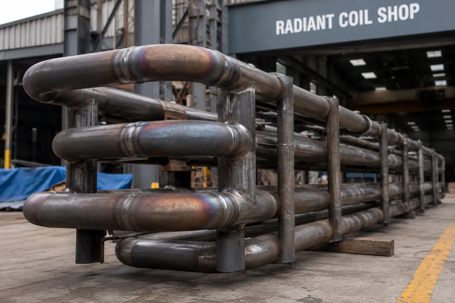
During this short interval, the hydrocarbon mixture must absorb enough energy to drive an endothermic cracking reaction, while the tube wall may reach 950–1100 °C and the process tube metal may exceed 1000 °C.
This is the central mechanical problem in ethylene cracking furnace radiant coil design: the coil must transfer heat rapidly, but not so unevenly that the tube loses its structural margin. The engineering objective is not maximum temperature in isolation. It is controlled heat flux, controlled residence time, and stable tube-metal temperature over the full operating surface.
The mechanics of an ethylene cracking furnace radiant coil are therefore inseparable from metallurgy, burner arrangement, refractory condition, coil geometry, and coke management. A coil that transfers heat aggressively but develops local hot spots is not a high-performance coil. It is a failure mechanism with a short delay.
The Physics of Endothermic Conversion in Radiant Sections
Thermal cracking consumes heat. The hydrocarbon feed does not simply pass through a hot tube and emerge as ethylene. It undergoes a temperature-dependent sequence of reactions in which the available thermal energy must be transferred through the tube wall and into a moving process stream.
The radiant section supplies most of this energy through radiation from the furnace enclosure and flame environment. The tube receives radiant energy at its external surface. That energy conducts through the tube wall and enters the hydrocarbon mixture by convection. The process side then distributes the absorbed energy through turbulent and molecular transport within the flowing feed.
Each step creates a resistance to heat transfer:
- The furnace atmosphere must deliver radiant energy to the external tube surface.
- The tube wall must conduct that energy without excessive temperature gradient.
- The internal film must transfer energy into the hydrocarbon stream.
- The feed must absorb the energy quickly enough to reach the target outlet temperature within the available residence time.
The radiant section is designed around this chain. The heat flux is not an abstract furnace rating. It is the rate at which energy crosses a defined tube surface area. If the flux is too low, the feed may leave below the intended cracking temperature or require longer residence time. Longer residence time increases the opportunity for secondary reactions and coke formation.
If the flux is too high, the external tube wall can reach a temperature at which alloy creep accelerates, surface oxidation becomes more severe, or the local process-side temperature rises beyond the intended reaction profile. Excessive local heating also produces an uneven thermal field. The average heat flux may remain within a design target while individual tube zones operate at substantially higher intensity.
High flux is useful only when it is distributed. A high average with severe local peaks is a tube-life problem, not a conversion strategy.
The commonly cited design limit for average radiant coil heat flux is around 85 kW/m². This value should not be treated as a universal operating setpoint. It is a practical upper boundary used to balance conversion intensity against acceptable run length, tube-metal temperature, and coking tendency. The permissible value depends on coil geometry, alloy, furnace arrangement, feedstock, steam dilution, burner pattern, and the quality of temperature monitoring.
Why rapid heat transfer matters
Thermal cracking is highly sensitive to both temperature and exposure time. The feed must reach the cracking regime quickly and pass through it without unnecessary delay. A slow temperature rise can reduce the effectiveness of the radiant section. A long residence time at elevated temperature can increase secondary reactions.
This produces a design tension:
1. The feed requires enough energy to reach a coil outlet temperature of approximately 820–870 °C.
2. The coil must deliver that energy over a short path.
3. The hydrocarbon should not remain at high temperature longer than the process requires.
4. The tube wall must remain below the temperature at which creep and metallurgical degradation become dominant.
The coil therefore functions as a controlled thermal exposure system. Its geometry is not selected only for pressure drop or fabrication convenience. It establishes how quickly the feed is heated, how long it remains in the reaction zone, and how much tube surface is available for energy transfer.
Balancing Heat Flux Limits and Hydrocarbon Residence Time
Residence time in the radiant coil can vary significantly with furnace and coil configuration. Two-pass CBL coils may operate with residence times in the range of approximately 0.2–0.5 seconds. Single-pass Millisecond coils can reduce the residence time to below 0.1 seconds.
That difference changes the mechanical requirements of the furnace. A very short residence time requires rapid energy transfer and a carefully controlled temperature profile. The coil cannot depend on long exposure to compensate for weak heat transfer. The radiant section must place sufficient energy into the feed almost immediately.
A longer residence time provides more opportunity for heat absorption, but it also increases the period during which the hydrocarbon mixture is exposed to conditions that can promote secondary reactions and internal carbon deposition. It may allow a less intense heat-transfer profile, but it does not remove the need for thermal uniformity.
The correct design relationship is not simply:
higher heat flux = better cracking
It is closer to:
required heat transfer + controlled residence time + acceptable tube-metal temperature = viable coil operation
A useful comparison is shown below.
| Parameter | Two-pass CBL-type coil | Single-pass Millisecond-type coil |
|---|---|---|
| Approximate residence time | 0.2–0.5 seconds | Below 0.1 seconds |
| Thermal demand | More distributed heating over a longer path | Very rapid heat input |
| Main design sensitivity | Residence-time distribution and outlet temperature | Local heat flux and short-path temperature control |
| Typical failure concern | Uneven heating, coke accumulation, and prolonged high-temperature exposure | Localized overheating and limited tolerance for flux imbalance |
| Required control focus | Flow distribution, pass balance, and decoking interval | Burner symmetry, tube-metal temperature, and radiant uniformity |
The comparison does not establish that one coil type is inherently superior. It shows that each geometry shifts the dominant constraint. The shorter the residence time, the less freedom the design has to tolerate local inefficiency. A small loss of heat transfer in a millisecond coil can directly alter the outlet temperature profile.
Heat flux is a spatial variable
An average heat flux value conceals the actual distribution along the coil. In practice, the furnace wall, burner rows, refractory surfaces, tube spacing, flame shape, and draft pattern determine whether the coil receives uniform radiant exposure.
The same nominal furnace duty can produce different tube conditions if:
- burners are misaligned;
- flame lengths differ between rows;
- refractory surfaces have degraded or changed emissivity;
- tube spacing creates unequal view factors;
- the feed flow is divided unevenly between parallel passes;
- deposits alter the external surface condition;
- convection-section conditions shift the radiant-section inlet temperature.
A local increase in external heat flux raises the tube-wall temperature. The process-side response may not compensate immediately because the feed flow and composition remain constrained by the coil design. The result is a local temperature gradient rather than a uniform increase in useful reaction rate.
This is why coil design requires more than a furnace-wide heat balance. The thermal field must be considered at tube-row, pass, and local surface levels.
Metallurgical Requirements for 1100 °C Operating Environments
The tube is both a pressure boundary and a heat-transfer surface. It must withstand internal pressure, high temperature, thermal cycling, carburizing or coking exposure, and the mechanical effects of differential expansion.
At tube-metal temperatures above 1000 °C, conventional carbon steel is not a viable material for the process coil. Ethylene cracking radiant tubes are manufactured from high-temperature alloys selected for their creep strength, oxidation resistance, carburization resistance, and stability under repeated decoking cycles.
The outer tube wall may reach 950–1100 °C. Some alloy systems are designed for maximum operating temperatures approaching 1200 °C. That upper limit is not a target for routine operation. It represents a boundary within which the material may retain a defined level of performance under specified conditions.
The difference matters. A material rating does not authorize uncontrolled temperature excursions. The remaining tube life depends on the actual temperature history, stress state, wall thickness, internal deposits, thermal gradients, and operating duration.
Creep is a time-dependent failure mechanism
At high temperature, the tube does not behave as a perfectly elastic component. Under sustained internal pressure, the metal can deform gradually. This is creep. The rate increases strongly with temperature and is affected by alloy microstructure, stress concentration, and exposure history.
A small increase in local tube-metal temperature can therefore have a disproportionate effect on remaining life. The critical variable is often not the average tube temperature but the hottest persistent zone.
Creep damage may develop alongside:
- tube swelling;
- changes in wall thickness;
- surface cracking;
- weld-area degradation;
- distortion at supports or return bends;
- loss of dimensional alignment;
- eventual rupture under pressure.
The design response is to maintain a thermal margin, minimize local hot spots, and use inspection methods capable of detecting changes before failure. A furnace that remains operational at a high average duty can still contain one tube section approaching a critical condition.
Centrifugally cast radiant tubes
Centrifugally cast radiant tubes are used because the manufacturing process can produce thick-walled, high-alloy components suited to severe thermal and mechanical service. Centrifugal casting distributes molten metal against a rotating mold, producing a tube with controlled wall geometry and a microstructure designed for high-temperature use.
The manufacturing process does not eliminate all service risks. Tube performance still depends on:
- alloy chemistry;
- casting quality;
- internal and external surface condition;
- dimensional control;
- weld and return-bend execution;
- support arrangement;
- operating temperature;
- carburization and coke exposure;
- decoking practice.
The tube is not an isolated material choice. Its life is the outcome of the entire mechanical system.
Thermal expansion must be allowed, not resisted
Radiant coils expand as their metal temperature rises. The movement is substantial because the coil is long, hot, and exposed to repeated operating cycles. Supports and guides must permit the intended expansion path while preventing excessive lateral movement, vibration, or contact with adjacent components.
A support that is too rigid transfers thermal movement into bending stress. A support that is too loose may permit rubbing, impact, or misalignment. Return bends and outlet connections are especially sensitive because they combine geometric curvature with pressure loading and thermal expansion.
The resulting design problem is similar to any high-temperature pressure boundary, but with a more severe thermal field. The coil must remain aligned while free to move. This requires accurate fabrication, controlled installation, and careful attention to support elevations after refractory and structural components are completed.
Mitigating Localized Hot Spots and Carbonaceous Coking
Coke formation inside radiant coils is not an optional maintenance issue. It is part of the process environment. Hydrocarbon cracking can produce carbonaceous deposits on the internal tube wall. These deposits reduce the effective flow area and add thermal resistance between the hot metal and the process stream.
As the coke layer thickens, the tube must develop a higher wall temperature to transfer the same amount of energy into the feed. The system can enter a reinforcing cycle:
1. Coke deposits increase thermal resistance.
2. Heat transfer to the process stream becomes less effective.
3. Tube-metal temperature rises for the same furnace duty.
4. Higher metal temperature accelerates creep and may promote further deposit growth.
5. The deposit increases pressure drop and disturbs flow distribution.
6. Uneven flow creates additional thermal imbalance between parallel tubes or passes.
This mechanism explains why a coil can deteriorate even when the burner duty has not changed. The thermal resistance has moved from the furnace side to the process side.
Uneven external heat flux produces a related problem. A hot spot increases the local wall temperature. The internal surface in that region may become more prone to carbonaceous deposition. The deposit then insulates the tube and pushes the metal temperature higher. The result is a coupled thermal and chemical failure mode.
Coking mitigation is not only a chemistry problem. It is also a heat-transfer, flow-distribution, and tube-temperature problem.
Internal and external causes must be separated
Operators often see a high tube-metal temperature and immediately associate it with burner duty. That interpretation is incomplete. The same symptom may result from several different mechanisms:
- excessive local radiant exposure;
- insufficient hydrocarbon flow through a pass;
- uneven feed distribution;
- coke insulation on the internal wall;
- damaged or displaced refractory;
- flame impingement;
- altered draft or combustion conditions;
- an outlet restriction;
- instrumentation error.
The corrective action depends on identifying the mechanism. Reducing furnace duty may lower the temperature temporarily while leaving a flow restriction or coke layer unresolved. Increasing flow may improve cooling in one pass but create a pressure or residence-time imbalance elsewhere.
A useful diagnostic approach compares multiple variables rather than relying on one temperature reading:
- tube-metal temperature by location;
- outlet temperature by pass;
- pressure drop across the coil;
- burner flame pattern;
- furnace draft;
- fuel and combustion-air distribution;
- decoking history;
- feed flow and steam dilution;
- trends during load changes.
No single measurement defines coil health. The pattern across measurements is more informative.
Decoking restores thermal behavior, but not indefinitely
Periodic decoking is required for ethylene cracking furnaces. It removes internal deposits and restores part of the original heat-transfer and flow conditions. It does not make the coil permanently resistant to coking, and it does not reverse all metallurgical damage accumulated during the run.
Decoking itself creates thermal and chemical stress. Rapid temperature changes can impose additional strain on tubes, welds, supports, and refractory components. The procedure must therefore be controlled. Aggressive cleaning that removes deposits quickly but creates severe thermal gradients may trade one degradation mechanism for another.
The correct decoking interval is linked to the actual condition of the coil. Indicators include rising tube-metal temperature at constant duty, increasing pressure drop, falling throughput, changing outlet temperature, or worsening pass imbalance. A fixed calendar interval is less informative than a trend based on process and mechanical data.
Optimizing Coil Geometry for High-Yield Cracking Efficiency
Coil geometry determines the relationship between heat-transfer area, flow path, pressure drop, residence time, and mechanical expansion. It also controls how the tube surface is exposed to the furnace radiation field.
A high-flux design must solve several competing requirements:
- enough surface area to transfer the required energy;
- a short enough path to limit unwanted secondary reactions;
- sufficient internal velocity to control film resistance and deposit behavior;
- acceptable pressure drop;
- uniform flow distribution among parallel passes;
- a support arrangement that allows thermal movement;
- access for inspection and replacement;
- compatibility with the furnace structure and refractory envelope.
The radiant coil cannot be optimized by one variable. Increasing tube length may add heat-transfer area but also increase residence time and pressure drop. Reducing the number of passes may shorten the path but raise the demand on local heat flux. Changing tube spacing can alter radiation view factors and create differences between front and rear rows.
Geometry controls residence-time distribution
Nominal residence time is not the same as actual residence-time distribution. Two tubes may have the same designed length and diameter but expose the feed to different conditions if flow division is uneven or if one pass contains more coke.
The process stream should move through the coil without large stagnant zones or severe velocity differences. Low-velocity regions can experience greater deposit formation. High-velocity regions may create excessive pressure drop or shift the heat-transfer balance between passes.
Return bends are also important. They introduce local changes in direction and can create additional stress concentrations. Their position relative to burners and refractory surfaces affects both thermal exposure and mechanical expansion. A return bend placed near a high-intensity flame zone may become a localized structural risk even if the straight tube sections remain within acceptable conditions.
The convection section affects the radiant section
The radiant coil does not operate as a separate thermal machine. The feed arrives from the convection section at an inlet temperature commonly ranging from 500–680 °C, depending on process conditions and furnace design. If the convection section transfers more or less heat than intended, the radiant section receives a different thermal load.
A lower radiant inlet temperature requires additional heat input in the radiant zone to achieve the target coil outlet temperature. A higher inlet temperature reduces the remaining duty but may alter the reaction profile and the available thermal margin.
This interaction means that convection-section fouling, feed preheat imbalance, steam distribution, and flue-gas conditions can eventually appear as radiant-coil problems. A radiant tube operating at an unusual temperature should not be assessed without reviewing upstream preheating conditions.
Furnace structure and refractory are part of coil performance
The coil is surrounded by a structural and refractory system that defines its thermal environment. Industrial furnace design includes the radiant box, burner system, refractory lining, supports, headers, crossover components, convection modules, and roof or truss structure.
Refractory degradation changes the radiant environment. Cracks, gaps, spalling, or altered surface emissivity can shift the distribution of radiant energy. A tube may then receive more direct radiation from a flame or hot surface than the original design assumed.
The roof and support structure also affect alignment. Differential expansion between the furnace casing, tube supports, headers, and structural members can change clearances during operation. These changes may produce tube contact, support loading, or local stress at connections.
This is why field assembly of large furnace sections cannot be treated as a purely dimensional task. Site alignment, weld sequencing, support installation, refractory completion, and final cold-condition measurements all influence the hot operating geometry.
Manufacturing and Assembly Tolerances That Affect Thermal Performance
Radiant coil fabrication is usually associated with welding, bending, casting, and nondestructive examination. Those activities are essential, but the thermal consequences of dimensional error are equally significant.
A small positional deviation can change the distance between a tube and a burner, alter the view factor to a refractory wall, or reduce the clearance between adjacent passes. A mismatch at a return bend can introduce bending stress that becomes more severe after thermal expansion. A header connection that is forced into alignment can retain residual stress before the furnace reaches operating temperature.
Manufacturing control should therefore address both pressure-boundary integrity and thermal geometry:
- tube straightness and ovality;
- bend radius and return-bend orientation;
- wall-thickness consistency;
- weld penetration and profile;
- header and outlet alignment;
- support elevations;
- distance between tube rows;
- clearances to refractory and burner components;
- expansion gaps;
- surface condition before commissioning.
The purpose is not aesthetic precision. It is to preserve the intended heat-flux distribution and mechanical load path.
A coil assembled accurately in the workshop can still be misaligned in the furnace if field tolerances are not controlled. Large modules may experience transport distortion, lifting deformation, or support settlement. The installation sequence should account for these effects rather than assuming that every module remains geometrically neutral.
Instrumentation: Measuring the Mechanical State, Not Just the Process Result
Coil outlet temperature is an important process variable, but it is not a complete measure of tube condition. Two furnaces may produce the same outlet temperature with different tube-metal temperatures. One may be operating with clean internal surfaces and uniform heat flux. The other may be compensating for coke insulation with a higher metal temperature.
Tube-metal temperature monitoring is therefore central to high-flux operation. The measurement system should support trend analysis by location and by pass. A single alarm threshold is less useful than a sustained deviation from the normal relationship between:
- furnace duty;
- feed rate;
- outlet temperature;
- pressure drop;
- pass flow;
- tube-metal temperature;
- decoking interval.
Thermocouples and optical methods each have limitations. Sensor placement, calibration, shielding, sight lines, emissivity assumptions, and response time affect the result. Apparent temperature should not be treated as exact tube-metal temperature without understanding the measurement method.
The most valuable information often comes from changes over time. A gradual rise in temperature at constant operating conditions may indicate coke accumulation or a developing flow imbalance. A sudden rise in one area may indicate flame impingement, refractory damage, or an instrument problem. A uniform rise across the furnace may indicate a change in duty, feed preheat, draft, or ambient conditions.
A Practical Structural Review of a High-Flux Coil
A reliable review follows the heat path and the load path together. The following sequence is more useful than examining isolated components.
1. Define the thermal duty at the radiant inlet and outlet.
Confirm the feed temperature entering the radiant section, the target coil outlet temperature, the expected flow, and the steam-dilution condition. The radiant coil cannot be assessed without its inlet state.
2. Map the heat-flux distribution.
Review burner arrangement, flame shape, tube-row exposure, refractory condition, and any evidence of direct flame impingement. Average duty should not conceal local peaks.
3. Compare tube-metal temperature by location.
Persistent hot zones deserve more attention than short transient excursions. Compare corresponding tubes and passes, not only furnace-wide averages.
4. Check flow balance and pressure drop.
A thermal anomaly may originate from restricted or uneven flow. Rising pressure drop can indicate coke accumulation, while pass imbalance can change both residence time and cooling of the tube wall.
5. Assess alloy and manufacturing condition.
Confirm the tube material, casting or fabrication quality, weld condition, wall thickness, and evidence of carburization, creep, swelling, or cracking.
6. Review expansion and support behavior.
Look for contact marks, distorted guides, loaded supports, misaligned return bends, and unexpected movement at hot conditions.
7. Link the findings to the decoking history.
The timing of temperature rise, pressure-drop change, and performance loss can distinguish deposit-related degradation from a furnace-side thermal problem.
8. Separate immediate correction from life assessment.
Reducing duty may control the immediate temperature. It does not determine whether the tube has already accumulated irreversible creep or carburization damage.
This sequence keeps the analysis mechanical. It avoids treating a high outlet temperature, a high tube temperature, or a short run length as a diagnosis by itself.
The Design Logic Behind High-Flux Radiant Coils
High-flux ethylene cracking is necessary because the process must transfer substantial energy in a very short time. The feed is preheated in the convection section, enters the radiant coils at an elevated temperature, and must leave at a controlled coil outlet temperature after a residence time that may be below 0.1 seconds in millisecond configurations.
That duty places the tube in an extreme environment. The exterior wall may operate between 950 and 1100 °C. The process tube metal can exceed 1000 °C. High-temperature alloys may provide resistance up to approximately 1200 °C, but the usable margin depends on actual stress and exposure history. Average radiant heat flux around 85 kW/m² is a practical upper boundary for balancing conversion and run length, not a license to maximize furnace intensity.
The main engineering controls are consequently clear:
- distribute radiant heat rather than concentrating it;
- match heat flux to residence time and feed condition;
- control tube-metal temperature, not only outlet temperature;
- select alloys for creep, oxidation, carburization, and thermal cycling;
- preserve flow balance between passes;
- design supports for expansion;
- maintain refractory and burner geometry;
- treat coking as a coupled chemical and thermal problem;
- use decoking to restore performance without assuming full life recovery;
- inspect the tube as a time-dependent pressure boundary.
The radiant coil is successful when it maintains this balance over an operating run. Conversion efficiency matters, but so does the stability of the mechanical system that produces it. A furnace that reaches the target outlet temperature by consuming tube life is not operating efficiently. It is converting feedstock at the expense of its pressure boundary.
The decisive question is therefore not whether the coil can tolerate high flux for a short period. It is whether the complete furnace system can sustain the required flux with uniform heat distribution, predictable residence time, controlled coking, and a defensible tube-metal temperature margin. That is the real meaning of high-flux ethylene cracking furnace radiant coil mechanics.