PAUT or Radiography: Is Phased Array Worth It for Vessel Welds?
The question of phased array ultrasonic testing versus radiography for pressure vessels is no longer simply a choice between two inspection instruments.
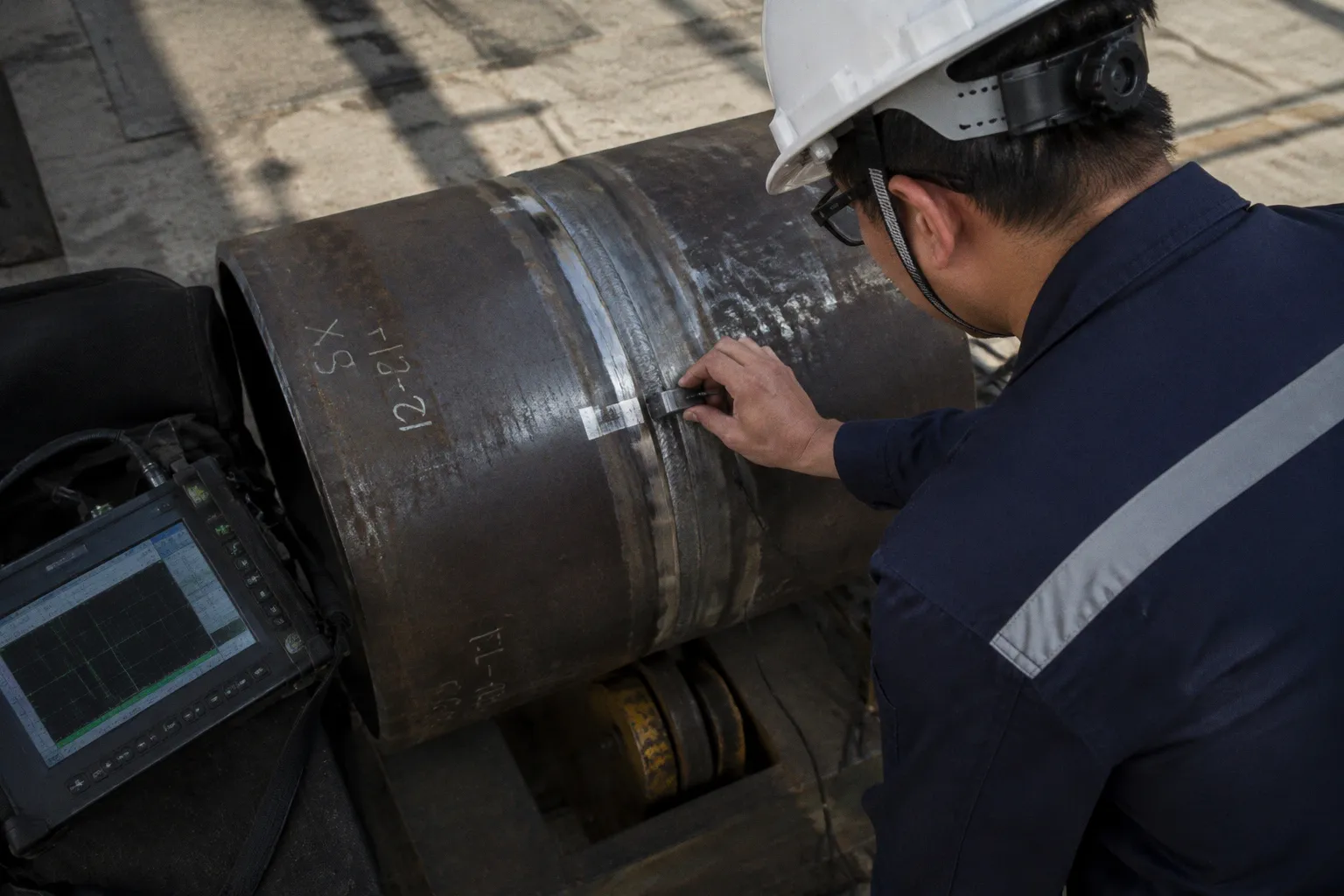
It is a decision about what kind of information the weld must provide, how the inspection will fit into production, and whether the resulting data can support a defensible engineering decision when a discontinuity is found.
Radiography remains familiar for good reason. It produces an image that is relatively easy to archive and interpret for volumetric imperfections such as porosity and inclusions. But pressure-vessel welds do not fail only through volumetric defects. Cracks, lack of fusion, and other planar flaws can be more critical, particularly when their orientation allows them to open under service loading. This is where phased array ultrasonic testing, or PAUT, begins to settle into a different role — not as a universal replacement for radiographic testing, but as a more informative method for many thicker welds and more demanding integrity assessments.
The practical comparison, then, is not PAUT versus RT in the abstract. It is phased array ultrasonic testing versus radiography for pressure vessels under a defined material thickness, weld geometry, code requirement, production environment, and defect-risk profile.
The standards have made room for a different inspection path
For pressure-vessel and boiler welds, the most important threshold is often the least dramatic one: material thickness.
ASME Code Case 2235 permits ultrasonic examination, including PAUT and TOFD-based approaches, in lieu of radiography for qualifying welds in materials at least 0.5 inches thick — 12.7 mm, commonly rounded to 13 mm. That threshold does not mean every weld above this thickness automatically qualifies for PAUT, nor does it mean radiography has become unnecessary. It means that, under the conditions defined by the applicable code case and project specification, ultrasonic examination can be accepted as an alternative route.
The distinction matters because code compliance is not a matter of choosing the inspection method that appears more advanced. The procedure, equipment, calibration, operator qualification, scanning coverage, evaluation criteria, and reporting method all have to align with the governing requirements. ASME Section V Article 4 incorporates ultrasonic inspection processes into the main body of the code for volumetric examination, while the relevant construction code — including ASME BPV Sections I, III, or VIII, depending on the vessel and service — establishes how those examination results are used.
A fabrication team may therefore be looking at several overlapping questions:
- Is the weld thickness within the range where UT can be used in lieu of RT under the applicable rules?
- Does the weld geometry allow the required ultrasonic beam coverage?
- Has a written PAUT procedure been developed and qualified for the joint configuration?
- Are the acceptance criteria coming from the correct construction code, specification, or engineering basis?
- Will the owner, authorized inspector, and jurisdiction accept the selected examination route?
- Does the inspection record need an image, a digital data set, a weld map, or all three?
These are not administrative details placed around the inspection. They determine whether the inspection can be trusted when the component moves from fabrication into service.
PAUT is not valuable merely because it is newer. It is valuable when the weld requires information that a two-dimensional radiographic image cannot provide as clearly.
The industry shift toward PAUT has developed because ultrasonic methods can be shaped around the defect types and engineering questions that matter most. A phased array probe may use 16, 32, or 64 elements, firing them with controlled time delays to steer and focus the sound beam through the weld volume. Instead of relying on a single fixed beam, the examiner can build a sequence of angles and focal laws designed for the joint.
That flexibility does not remove the need for disciplined procedure development. It makes the procedure more consequential.
Planar defects and volumetric defects are not the same inspection problem
The clearest technical difference in PAUT versus RT weld inspection is the type of discontinuity each method tends to reveal most effectively.
Radiographic testing is strong at showing volumetric discontinuities. Porosity, slag or other inclusions, and similar three-dimensional density variations can appear clearly in the radiographic image because they change the way radiation passes through the weld. For certain joint configurations and thickness ranges, that image is direct, familiar, and still highly useful.
Ultrasonic testing, including phased array techniques, is generally more effective for planar flaws such as cracks and lack of fusion. These reflect ultrasonic energy when their surfaces are oriented in a way that interacts with the beam. A properly designed PAUT scan can examine the weld from multiple angles, improving the chance of detecting flaws that might be difficult to present in a favorable orientation on a radiograph.
The phrase properly designed carries the weight here. Ultrasonic detection depends on beam angle, sound path, material condition, surface access, attenuation, geometry, and the orientation of the discontinuity. A planar flaw that is poorly oriented relative to the examination beam may remain difficult to detect. Conversely, a radiographic image may reveal a planar indication weakly or not at all if the flaw does not create a meaningful path-length difference for the radiation.
A useful comparison looks like this:
| Parameter | PAUT | Radiography |
|---|---|---|
| Strongest defect response | Planar flaws such as cracks and lack of fusion | Volumetric flaws such as porosity and inclusions |
| Primary output | Encoded ultrasonic data, sectorial scans, flaw position and sizing information | Radiographic image showing density variations and projected indications |
| Through-wall information | Can provide three-dimensional flaw-height data | Primarily a two-dimensional projection |
| Radiation hazard | None | Requires control of radiation exposure and exclusion areas |
| Worksite interruption | Often allows nearby work to continue, subject to site controls | May require evacuation or restricted access around the exposure area |
| Thickness consideration | Under Code Case 2235, UT in lieu of RT applies to qualifying welds at least 0.5 inches thick | Remains widely accepted across many applications, including thin-wall components |
| Dependence on procedure | High — beam design, calibration, coverage, and interpretation are central | High — exposure technique, image quality, source placement, and interpretation are central |
| Engineering use | Well suited to sizing and fitness-for-purpose assessments when data quality supports it | Strong for visualizing volumetric indications in a stable, archivable image |
This is why a simple claim that PAUT has better flaw detection accuracy than radiography is too blunt to be useful. Accuracy is not one fixed property of the method. It changes with the defect type, thickness, weld profile, access conditions, material, scan plan, and qualification of the procedure and examiner.
For a vessel weld where lack of fusion at a fusion boundary is the dominant concern, PAUT may offer a more favorable inspection approach. For thin-wall fabrication where porosity and inclusions are the primary concern and radiographic access is straightforward, RT may remain the cleaner answer. The method should settle around the failure mode, not around the marketing language attached to the equipment.
Beam coverage is where the comparison becomes real
On a drawing, a weld may look like a simple line. In the inspection plan, it becomes a volume with surfaces, bevels, weld caps, heat-affected zones, backing conditions, access restrictions, and possible dead zones.
PAUT allows the inspection team to construct multiple refracted angles and focus positions, often creating a sectorial view of the weld. This can support broad coverage from one or both sides, depending on the configuration. But the scan must still reach the areas that matter. A beautifully rendered sectorial image does not compensate for a missed root region or an inaccessible portion of the heat-affected zone.
Radiography has its own geometric constraints. Source-to-object distance, film or detector placement, exposure direction, wall thickness, weld profile, and sensitivity requirements all influence image quality. A radiograph can be simple to review once it is acceptable, but obtaining that acceptable image may require careful positioning and repeated exposure planning.
The question is therefore not which method looks simpler in a brochure. It is which method gives the examination team the most reliable coverage for this joint, with the fewest blind areas and the clearest evaluation basis.
Safety and production: the exclusion zone changes the economics
The direct cost of PAUT versus RT is difficult to reduce to a universal percentage. Equipment investment, technician rates, procedure qualification, production scale, site access, reporting requirements, and reinspection rates all vary. A vessel manufacturer working in a controlled shop environment will not experience the same economics as a field contractor inspecting a large vessel inside an operating plant.
Still, the operational difference is substantial.
Radiographic testing uses ionizing radiation. During an exposure, the surrounding area may require an exclusion zone, controlled access, warning systems, and coordination with other trades. Work may stop around the inspection location, sometimes affecting welding, fit-up, lifting, coating, maintenance, or commissioning activities. The examination itself may be short, but the protected period around it can become the more disruptive part of the operation.
PAUT generates no radiation hazard. This allows concurrent work to continue around the inspection site without the radiation exclusion and evacuation requirements associated with RT, subject to the site’s general safety rules and the specific ultrasonic examination setup. In a busy fabrication yard, that difference can help the production sequence soften rather than tighten around the inspection team.
The benefit is not only faster movement of people. It is reduced friction between inspection and manufacturing. A vessel may have several welds awaiting examination while other crews are preparing adjacent components. With RT, the workfront may need to be cleared repeatedly. With PAUT, the inspection can often be integrated more continuously into fabrication, especially when access and surface preparation are planned from the beginning.
The economic comparison becomes more grounded when it is separated into its parts:
- Equipment and setup: PAUT requires a suitable flaw detector, probe assemblies, wedges, encoded scanners where applicable, software, calibration blocks, and qualified procedures. RT requires the radiation source or X-ray system, exposure accessories, detectors or film processing capability, and radiation-control infrastructure.
- Personnel: Both methods depend on competent examiners. PAUT interpretation requires comfort with encoded data, sectorial scans, beam behavior, and characterization of indications; RT requires disciplined image interpretation and exposure-quality control.
- Production interruption: RT can impose exclusion zones and work stoppages. PAUT generally avoids radiation-related shutdowns, which may be decisive in a crowded facility.
- Data handling: PAUT produces substantial digital information that must be stored, reviewed, and traceable to the weld. RT produces an image that is straightforward to archive, though the image alone may contain less dimensional information about a planar flaw.
- Rework exposure: A method that finds a critical indication with clearer position and depth information may reduce uncertainty during excavation and repair, even if its initial deployment is not the least expensive line item.
This is why asking only, “Is PAUT cheaper than RT?” often leads the project in the wrong direction. A better question is whether PAUT can reduce the total inspection burden while improving the kind of information needed for acceptance, repair, or engineering assessment.
The deeper advantage: measuring flaw height through the wall
Radiography primarily presents a two-dimensional projection. It can show the length and apparent location of an indication in the image, but the projected image does not provide the same direct three-dimensional description of flaw height through the wall.
PAUT can provide through-wall sizing information — the height of a flaw as it extends through the material thickness — when the procedure, calibration, coverage, and data quality support that measurement. This changes the conversation after an indication is found.
Finding a flaw is only the first step. The next questions are usually more difficult:
- Where exactly is the indication in relation to the weld and heat-affected zone?
- How long is it?
- How high is it through the wall?
- Is it oriented in a way that makes it structurally significant?
- Can it be accepted under the applicable criteria?
- If it remains, can the component be demonstrated fit for purpose?
- If it is repaired, can the excavation be focused rather than unnecessarily enlarged?
Through-wall sizing can support Engineering Critical Assessment and Fitness-For-Purpose evaluations. That does not mean every PAUT result automatically qualifies for an ECA, or that sizing uncertainty disappears. It means the data can be more closely connected to the mechanics of a flaw in service.
A radiograph may tell the team that an indication exists and where its projection lies. A well-executed PAUT examination may add the dimensional information needed to decide whether that indication is tolerable, repairable, or structurally unacceptable. For pressure vessels, where the consequence of a crack-like defect can be more important than the mere presence of a density variation, that added dimension can settle the decision with greater clarity.
The quality of the sizing still matters. Indication height can be influenced by resolution, beam spread, surface condition, weld geometry, calibration, and the examiner’s interpretation. The data must be reviewed within the limits of the qualified technique. PAUT is not a device that turns uncertain information into certainty simply by displaying more colors on a screen.
The strongest case for PAUT appears after detection — when the project needs to understand the defect, not merely record that an image contains one.
This is also where digital traceability becomes useful. A PAUT data file can preserve scan information, position, amplitude responses, and reconstructed views in a way that supports later review. If an engineering team revisits the weld because service conditions change or a similar indication appears elsewhere, the original examination may contain more usable detail than a static image alone.
When PAUT becomes the better choice
The choice of phased array UT over RT is most persuasive when several conditions align rather than when one technology is declared superior.
PAUT deserves serious consideration when:
1. The weld is thick enough for the applicable code path. Under ASME Code Case 2235, the relevant minimum thickness for using ultrasonic examination in lieu of radiography is 0.5 inches, or 12.7 mm. This threshold must be read together with the rest of the code case and project requirements, not treated as a free-standing permission.
2. Planar defects are the main concern. If the engineering risk is concentrated around cracks, lack of fusion, or similar flaws, the directional and multi-angle capabilities of PAUT may provide more useful coverage than a conventional radiographic approach.
3. Radiation control would interfere with production. In a shop or site where other crews need to work nearby, eliminating RT exclusion zones can make the inspection sequence easier to coordinate and less disruptive.
4. The result may need to support a fitness-for-purpose decision. Through-wall flaw sizing can be valuable when the project must evaluate the significance of an indication rather than simply classify it against a binary acceptance criterion.
5. The joint geometry is suitable for ultrasonic coverage. Access, surface condition, weld profile, material attenuation, and scan paths all need to support the qualified procedure.
6. The project can support the data discipline. PAUT is not only an instrument and a probe. It is a procedure, a calibration system, an encoded or controlled scanning method where required, interpretation, reporting, and long-term data management.
RT may still be the more practical choice when the component is thin-walled, when volumetric discontinuities dominate the risk, when the geometry is difficult for ultrasonic beam coverage, or when the owner and governing requirements specifically call for radiography. RT also remains widely accepted and effective for visualizing volumetric flaws, and its familiarity can be valuable in projects with established inspection workflows.
The most mature programs do not turn this into a loyalty test. They define the weld category, failure modes, code route, and production constraints first, then choose the method that settles most naturally into that structure.
Building a defensible PAUT procedure
A pressure-vessel manufacturer considering radiographic testing replacement with PAUT under ASME should begin before fabrication, not when the weld is already waiting for examination.
The inspection procedure needs to be connected to the actual weld design. That includes material type, thickness, bevel preparation, welding process, joint access, expected flaw orientations, and the required scan surfaces. Automatic submerged arc welding, for example, may produce a consistent weld profile that supports repeatable scanning, but consistency does not remove the need to account for root geometry and fusion boundaries. Post-weld heat treatment may alter residual stress conditions and the timing of examination, while surface coatings or roughness can affect probe coupling and access.
A robust procedure typically establishes:
- probe frequency and element configuration;
- wedge and refracted-angle selection;
- focal laws and sectorial scan range;
- calibration and reference reflectors;
- scan indexing and coverage;
- sensitivity settings and transfer correction;
- methods for recording and evaluating indications;
- criteria for characterization and sizing;
- examiner qualification and review responsibilities;
- data retention and weld traceability.
The number of probe elements — commonly 16, 32, or 64 in PAUT setups — is only one part of the system. More elements do not automatically produce a better examination. The probe must be matched to the material, thickness, weld geometry, and intended beam coverage. A sophisticated instrument used with an unsuitable scan plan can still leave the critical region poorly examined.
Procedure qualification should also address the limitations that are easy to hide beneath clean digital images. Are the root and cap fully covered? Can the beam reach the sidewall fusion boundaries? Is there a geometric reflector that could mimic a flaw? Can the operator distinguish a weld profile response from a lack-of-fusion indication? Is the surface condition stable enough to maintain coupling? Does the report identify the location in a way that a repair crew can use without guesswork?
The answers should settle into the documentation before the inspection becomes a production bottleneck.
A balanced examination strategy may be more useful than a single-method policy
In some projects, the best answer is not to eliminate one method entirely. A defined combination may be appropriate when the weld population is varied or when the risk profile includes both planar and volumetric discontinuities.
For example, PAUT can provide detailed volumetric examination and through-wall sizing for qualifying thicker welds, while radiography may remain in the inspection plan for thinner components or specific weld categories where its image response is especially valuable. The final arrangement depends on the construction code, owner specification, authorized inspection requirements, and the engineering basis for acceptance.
What should be avoided is the informal assumption that two methods are interchangeable because both are called volumetric examination. They do not see the weld in the same way. They respond differently to orientation, geometry, density, and access. Their records also support different kinds of later decisions.
A comparison matrix can help the project team keep the choice anchored:
| Project condition | PAUT tendency | RT tendency |
|---|---|---|
| Thick pressure-vessel weld, 0.5 inches or greater | Strong candidate if code, procedure, and coverage requirements are met | Still possible and widely accepted |
| Primary concern is lack of fusion or cracking | Often more informative because of multi-angle ultrasonic response | May be less favorable when flaw orientation produces weak radiographic contrast |
| Primary concern is porosity or inclusions | Detectable, but interpretation depends on ultrasonic response and geometry | Often strong because volumetric density changes appear in the image |
| Inspection beside active work areas | No radiation exclusion zone; concurrent work may continue | May require controlled access and work stoppage |
| Need for flaw-height data | Can support through-wall sizing and ECA when properly performed | Primarily provides a projected two-dimensional image |
| Thin-wall component | Applicability must be reviewed carefully | Often remains a practical and accepted method |
| Difficult ultrasonic access or severe geometry | May require a different scan plan or another method | May offer a simpler exposure arrangement, depending on access |
| Need for digital engineering review | Encoded data and reconstructed views can support later analysis | Archived image offers a clear visual record, with less direct height information |
The table is not a substitute for a procedure review. It is a way of keeping the decision from narrowing too early around equipment familiarity or purchase price.
So, is phased array worth it?
For qualifying pressure-vessel welds above the 0.5-inch threshold, PAUT can be worth the investment when the project needs stronger sensitivity to planar flaws, reduced disruption from radiation controls, and more useful information about flaw height through the wall. Its value grows when inspection data must feed an engineering critical assessment or a fit-for-purpose decision rather than stop at an image-based indication report.
But PAUT is not automatically the right answer for every vessel weld. Radiography remains effective for volumetric discontinuities, remains widely accepted for many applications, and may be better suited to thin-wall components or geometries that do not offer reliable ultrasonic coverage. The question is not whether RT has become obsolete. It has not.
The more grounded conclusion is this: PAUT earns its place when its particular strengths match the weld’s actual risk and the project’s working conditions. A manufacturer that chooses it only to avoid radiation barriers may still be choosing too narrowly. A manufacturer that chooses it because the weld demands planar-defect detection, dimensional flaw characterization, and a more continuous inspection workflow is making a more durable decision.
Begin with the defect that could matter most. Let the weld geometry, thickness, code route, and production environment settle around that concern — and allow the inspection method to become an anchor for sound engineering judgment, rather than another decision made by habit.