Crawler Cranes vs Strand Jacks for Heavy Column Lifting
A petrochemical column weighing more than 1,000 tons is not simply a large load. It is a moving structural system with changing support reactions, variable center-of-gravity behavior, temporary…
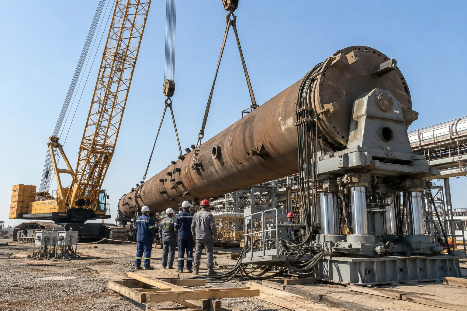
A petrochemical column weighing more than 1,000 tons is not simply a large load. It is a moving structural system with changing support reactions, variable center-of-gravity behavior, temporary stress paths, and severe consequences for small alignment errors.
The choice between a crawler crane and strand jacking therefore cannot be reduced to rated capacity. The relevant question is mechanical: how must the column move, what temporary structure can carry the reaction forces, how much ground is available, and how precisely must the vessel be positioned at the end of the lift?
Crawler cranes provide mobility, suspended-load travel, and a wide range of operating radii. Strand jack systems provide high vertical capacity from a compact footprint and allow multi-point synchronization through a central control system. Their operating mechanics are fundamentally different. One system moves a suspended load through boom geometry and tracked travel. The other raises the load through linear hydraulic strokes along high-tensile steel strands.
The correct lifting system is determined by the required movement path, not by the headline capacity printed in the equipment brochure.
Operational mechanics: incremental hydraulic cycles versus lattice-boom versatility
A crawler crane carries its load through a lattice boom, hoist ropes, upper machinery, revolving frame, crawler undercarriage, and prepared ground. The load is suspended from the boom tip. Its position changes as the crane slews, luffs, travels, or adjusts the hoist line.
This gives the crawler crane a degree of three-dimensional flexibility that strand jacks do not possess. A crawler crane can pick a column, travel a short distance with the load suspended, and place it within the working envelope defined by the boom and rigging arrangement. This pick-and-carry function is particularly valuable when a petrochemical module must be transferred from a transport position to a foundation or temporary assembly area without intermediate support.
The flexibility has a cost. Every change in radius alters the load moment. The crane’s rated capacity depends on boom length, operating radius, counterweight, track orientation, wind conditions, ground condition, and the exact rigging configuration. A 1,000-ton crane is not a universal 1,000-ton lifting solution. Its permissible load may be substantially lower at a large radius than near the crane’s centerline.
A strand jack works through a different load path. The jack body is connected to a reaction frame, lifting tower, gantry, or another engineered overhead structure. Steel strands pass through the jack. Upper and lower wedge anchors alternately grip and release the strand bundle as hydraulic cylinders extend and retract.
The movement is incremental:
1. The lower or upper anchoring system grips the strands and transfers load into the jack.
2. Hydraulic cylinders extend or retract through a defined stroke.
3. The opposite anchoring system engages before the first releases.
4. The jack resets for the next stroke.
5. The cycle repeats until the vessel reaches the required elevation.
This is not a suspended swing. It is a controlled vertical translation along the strand lines. A strand jack cannot slew a column or alter its load radius in the same way as a crawler crane. Horizontal movement requires separate equipment, such as skid tracks, hydraulic gantries, strand-based pulling systems, or a combination of temporary transport structures.
The distinction matters during petrochemical column lifting. If the column must be raised vertically from a horizontal position, both systems may be technically adaptable, but the temporary works are different. A crawler crane may use a tailing arrangement, lifting beam, main hook, and controlled rotation. A strand jack system may require a specially designed frame and multiple lifting points capable of maintaining vessel geometry during rotation or verticalization.
The lifting path must be modeled before equipment selection. The center of gravity may not remain directly between the lifting points. Internal trays, ladders, platforms, insulation, piping supports, and other attachments can shift the mass distribution. The column shell may also experience local stresses around lifting lugs that are not visible in a simple gross-weight calculation.
What the movement path favors
| Requirement | Crawler crane | Strand jack system |
|---|---|---|
| Vertical lift from fixed points | Possible, with suspended-load dynamics | Highly suitable when reaction frame is available |
| Short-distance travel with load suspended | Native pick-and-carry capability | Not a native function |
| Slewing and radius adjustment | Available within rated configuration | Not available without additional systems |
| Compact working footprint | Usually limited by crane size and access | Often compact at the lifting points, but requires reaction structure |
| Multi-point load control | Possible through rigging and crane configuration, but less direct | Strong capability with synchronized jacks |
| Incremental positioning | Controlled by crane operator and rigging system | Precise hydraulic stroke control |
| Dependence on overhead temporary steel | Not always required | Usually required for reaction and load transfer |
| Ground preparation | Significant for heavy lattice-boom cranes | Concentrated beneath towers, frames, or support points |
A crawler crane is therefore a mobile lifting machine. A strand jack is a vertical force-and-displacement system. Treating them as interchangeable obscures the engineering problem.
Ground bearing dynamics and site footprint
Ground condition is often the first practical constraint in a heavy lift. The crane’s own mass, the suspended column, counterweight, boom configuration, and dynamic effects are transferred through the crawler tracks into the soil or engineered working platform.
Crawler tracks distribute load more evenly than outriggers or conventional wheeled crane tires. This lowers average ground bearing pressure compared with a concentrated outrigger reaction. It does not eliminate the need for ground engineering. Large lattice-boom crawler cranes still require compacted soil, engineered crane mats, access roads, turning areas, and a working pad capable of carrying both static and changing loads.
The relevant condition is not only whether the ground can carry the crane while stationary. It must also tolerate movement. A crane traveling with a suspended vessel changes its support reactions as the load shifts, the tracks pass over irregularities, and the boom orientation changes. Differential settlement can create a small angular deviation at the load. In a tall petrochemical column, that deviation can amplify through the rigging geometry and increase side loading at lifting lugs.
Ground preparation must be integrated with the lift plan. A working pad that is adequate for crane assembly may not be adequate for the fully configured crane during the critical pick. Access for self-assembly, transport of lattice sections, counterweight delivery, and emergency load lowering must also be included. A crane plan that fits on the plot in two dimensions may fail when the assembly corridor, tail swing, and exclusion zone are added.
Strand jacks transfer their primary lifting reactions into towers, frames, or other structural supports. This can reduce the area needed for the lifting machinery itself. Individual strand jack capacities vary widely. Mammoet lists units from 15 to 900 tons in its fleet, while Enerpac identifies models from 17 to 1,405 imperial tons, equivalent to approximately 150 to 12,500 kN per unit.
Those figures describe the jack unit. They do not describe the capacity of the complete lifting system.
The temporary reaction frame may govern. So may the strand bundle, anchorage, lifting lug, support tower, foundation, weld detail, or local shell reinforcement. Every force must follow a continuous load path from the vessel into the jack, through the frame, and into the ground or permanent structure. A high-capacity jack connected to an under-designed tower is not a high-capacity lifting system.
Strand jacking is attractive on congested petrochemical sites because the system can operate with a smaller equipment footprint and without a large crane tail swing. The trade-off is concentration. Loads are introduced into a limited number of towers or support locations. Foundation stiffness and differential settlement become central concerns.
The support system must be checked for:
- Vertical compression and local bearing beneath each tower or frame.
- Differential settlement between lifting points.
- Lateral stability from wind, geometric imperfections, and accidental side loads.
- Temporary bracing during erection and dismantling.
- Load redistribution if one jack pauses, trips, or deviates from the programmed position.
- Foundation capacity during the full lifting sequence, not only at the final elevation.
A compact jack footprint does not mean a low-demand foundation. It usually means the reaction is more concentrated and therefore more sensitive to local stiffness.
Synchronized control for multi-point vessel installation
Heavy columns are rarely simple single-point lifts. Their length creates bending sensitivity. Their shells may be relatively thin compared with their overall height. Internal attachments and external platforms can introduce eccentricity. The lifting system must control not only total force but also relative displacement between lifting points.
Strand jack installations are well suited to this problem when the temporary works are properly designed. Multiple jacks can be connected to a central computerized control system. Systems are available for synchronous control of up to 60 strand jacks. The controller monitors stroke, pressure, and relative position, then adjusts hydraulic operation to maintain the programmed relationship among the lifting points.
This creates a more direct relationship between movement and control. If one point rises faster than another, the system can detect the deviation and compensate through hydraulic commands. The control logic does not remove the need for engineering judgment. It does, however, make multi-point vertical movement measurable and repeatable.
The control sequence should define permitted deviations, hold points, communication protocols, and stop conditions. A heavy vessel should not continue moving simply because the total load remains within the system’s rated capacity. A small difference in elevation can generate torsional or bending effects that exceed the assumptions used for the lifting lugs or temporary spreader beams.
The practical control sequence usually includes:
1. Preload and verification. Each jack is brought into contact with the load, and the measured reactions are compared with the expected distribution.
2. Initial lift. The vessel is raised only a short distance to verify stability, rigging behavior, and support response.
3. Controlled hold. The system stops while surveyors confirm elevation, inclination, and lateral displacement.
4. Incremental lifting. The programmed stroke cycle continues with defined monitoring intervals.
5. Alignment checks. The vessel axis, nozzle orientation, anchor-bolt relationship, and support elevation are checked before final lowering.
6. Load transfer. The vessel is lowered or seated onto permanent supports in a controlled sequence.
7. Temporary system release. Strand tension is removed only after the permanent load path is confirmed.
Crawler cranes also require disciplined load control, but their feedback mechanism is different. The crane operator works with load charts, radius indicators, boom angle, hoist line behavior, rigging signals, and survey data. Multi-crane lifts can be coordinated, but the system becomes more complex because each crane has its own movement, structural response, and control interface.
A single crawler crane may be mechanically simpler than a distributed strand jack system when the vessel can be lifted within a manageable radius. A tandem crawler lift, however, introduces load-sharing problems similar to those encountered in multi-point jacking. The lifting plan must define which crane carries which reaction at each stage and how the load changes as the vessel rotates or moves.
The installation tolerances are not controlled by lifting equipment alone. Surveying, foundation preparation, anchor-bolt positioning, support steel fabrication, and nozzle protection all influence final fit-up. A hydraulically synchronized lift can place the vessel at a precise elevation, but it cannot correct an anchor-bolt group that was embedded outside its intended geometry.
Strategic selection: mobility against vertical capacity
The central comparison in a crawler crane versus strand jacking heavy lift is not speed. Strand jacking uses incremental hydraulic strokes. It should not be assumed to be faster per meter than a crawler crane. The advantage is control, high vertical capacity, and the ability to work where a crane’s ground pressure, radius, or boom envelope is unacceptable.
A crawler crane is favored when the site provides a strong working platform and the vessel must move through a changing horizontal position. This includes short-distance pick-and-carry operations, transfer from a delivery route, placement into a module bay, or work where the crane can assemble close to the final foundation.
A strand jack is favored when the lift is predominantly vertical, the load is extremely heavy, the available footprint is restricted, or precise multi-point control is more important than mobility. It is also useful when an overhead reaction frame can be integrated into the temporary works without obstructing process construction.
The selection should be based on a defined set of mechanical conditions:
- Load mass and configuration. Use the complete lifted weight, including rigging, spreader beams, temporary platforms, insulation, ladders, and any attached equipment.
- Center of gravity. Confirm the actual or conservatively bounded center of gravity. Do not assume that the geometric center of a column is the mass center.
- Movement path. Define whether the operation requires vertical lifting only, rotation, slewing, short-distance travel, skidding, or final horizontal translation.
- Lifting-point capacity. Check local shell reinforcement, lug geometry, welds, pins, and load angles.
- Working radius. For a crawler crane, radius is a primary capacity variable. The critical radius may occur during initial pick, slewing, or final placement rather than at maximum elevation.
- Ground bearing and settlement. Assess both the machine platform and the support points for temporary towers or reaction frames.
- Wind exposure. A tall column has substantial projected area. Wind can create lateral forces and pendulum behavior in a suspended crane lift. It can also destabilize a strand jack frame.
- Assembly and dismantling. A crane requires transport and assembly space for boom sections and counterweights. A strand jack system requires erection of towers, beams, anchors, hydraulic power units, and control equipment.
- Recovery strategy. The plan must define how the load will be held or lowered after power loss, hydraulic fault, communication failure, or weather interruption.
- Interface with permanent works. Final elevation, anchor bolts, support skirts, base plates, and nozzle orientation must be compatible with the installation sequence.
A simple capacity comparison is inadequate. The system with the greater nominal lifting rating may be less suitable if it cannot perform the required movement without excessive temporary works.
When a crawler crane is mechanically advantageous
A crawler crane generally has the stronger case when:
- The vessel must travel while suspended.
- The final position is outside the practical location of a fixed lifting frame.
- The site can support a large engineered crane pad.
- There is sufficient access for assembly, counterweight handling, and boom erection.
- The lift requires slewing or radius adjustment.
- The column can be handled safely with a known rigging arrangement and acceptable load moments.
The crane’s movement flexibility reduces the need for a separate horizontal transfer system. That can simplify the overall method, even if the crane itself is large.
When strand jacking is mechanically advantageous
A strand jack system generally has the stronger case when:
- The lift is primarily vertical.
- The load is beyond the practical radius capacity of available cranes.
- The site is congested or lacks space for a large crawler crane.
- Ground conditions make crane travel or high-radius operation undesirable.
- The installation requires controlled multi-point synchronization.
- A suitable reaction frame or tower can be designed and erected.
- The vessel must be raised, held, and lowered with small incremental movements.
The system may also support modular construction strategies in which large assemblies are fabricated at grade and lifted into position after surrounding structures are partially complete. This can reduce work at elevation, but it transfers demand into temporary steel, foundations, and control engineering.
Engineering constraints in modular petrochemical construction
Modular construction changes the lifting problem before the lifting equipment arrives. A vessel may be delivered as part of a module with platforms, ladders, piping spools, cable trays, or structural steel already attached. The module’s transport stability and lifting stability are not automatically equivalent.
A crawler crane can be advantageous for a completed module because it can pick and carry the assembly from a prepared laydown area. But the module’s projected area and center of gravity may create a larger wind and overturning problem than the vessel alone. The rigging points must be designed for the complete module, not retrofitted from the lifting lugs used during vessel fabrication.
Strand jacking can support a top-down or vertical installation sequence, but the temporary frame must coexist with permanent steel and process equipment. Its tower locations may conflict with pipe racks, foundations, access roads, or future maintenance zones. The frame must be modeled as part of the construction sequence, not treated as isolated lifting hardware.
BIM construction simulation is useful here because the critical constraints are spatial and sequential. The model should show:
- Crane assembly and disassembly zones.
- Boom clearance from existing steel and process equipment.
- Track travel paths and mat transitions.
- Strand jack tower positions and bracing.
- The full vertical clearance required above the vessel.
- Rigging access and inspection points.
- Survey instrument locations.
- Emergency lowering or load-release paths.
- The sequence in which permanent supports become available.
The model should also be linked to the structural calculation. A visually clear lift path can still conceal a temporary load case that has not been checked. Conversely, a structurally adequate system may be impossible to assemble because the required beams cannot be brought into position after the module is erected.
Equipment installation tolerances need to be divided into separate categories. Vertical elevation, inclination, azimuth, nozzle orientation, support-seat contact, anchor-bolt alignment, and temporary support removal each require their own measurement and acceptance criteria. The lifting system controls some of these variables. It does not control all of them.
For example, synchronized strand jacks can maintain relative elevation among lifting points. They cannot compensate indefinitely for a permanently distorted support frame. A crawler crane can place a vessel within the foundation zone. It cannot force a misaligned skirt over anchor bolts without introducing unacceptable side loading.
The final positioning phase is often more sensitive than the main lift. Once the vessel is close to its permanent support, the available clearance decreases. Rigging angles change. Side loads become more difficult to detect. The correct approach is to reduce movement amplitude, increase survey frequency, and transfer load gradually. The vessel should not be allowed to become a free-moving suspended body during final fit-up.
A practical decision sequence for the lift plan
The selection process can be made more reliable by following the mechanics in order rather than starting with available equipment.
1. Define the required motion
Write the movement as a sequence of physical actions: pick, rotate, raise, travel, slew, skid, lower, and seat. If the sequence contains meaningful horizontal travel while the load is suspended, the crawler crane has a fundamental functional advantage. If the motion is almost entirely vertical, strand jacking becomes more competitive.
2. Establish the governing load cases
Calculate the complete lifted mass and identify the critical stages. The initial pick may govern a crawler crane because of radius. The final seating phase may govern a strand jack because of uneven support transfer. Include wind, temporary eccentricity, rigging angles, and possible differential displacement.
3. Trace every reaction into the ground
For a crawler crane, trace reactions through the tracks, mats, and working platform. For strand jacks, trace reactions through the anchors, jack bodies, temporary frames, towers, foundations, and soil. Do not stop the calculation at the lifting equipment.
4. Check the vessel itself
Confirm shell stresses, lug capacity, reinforcement, local buckling resistance, and deformation limits. A heavy column can have adequate global strength but inadequate local strength at a lifting lug or temporary support.
5. Test the construction sequence in three dimensions
Use BIM or equivalent spatial coordination to verify access, clearance, assembly, and dismantling. The lift is not feasible if the crane cannot be assembled or the strand jack frame cannot be removed after placement.
6. Define control and hold points
Assign responsibility for hydraulic control, crane operation, rigging signals, survey, geotechnical observation, structural inspection, and stop-work decisions. The control system must have a clear response to unequal jack stroke, unexpected pressure, ground movement, loss of communication, or weather deterioration.
7. Confirm the recovery method
A lift plan is incomplete without a controlled response to failure. Hydraulic systems require defined holding and lowering behavior. Crawler crane operations require a safe response to engine failure, power loss, wind increase, track settlement, or unexpected load behavior. Recovery should not depend on improvisation beside a suspended vessel.
Final position
Crawler cranes and strand jacks solve different mechanical problems.
The crawler crane is the more versatile system. It can pick, carry, slew, and place a load within a defined operating envelope. Its primary constraints are radius, ground preparation, assembly space, boom geometry, and suspended-load stability.
The strand jack is the more controlled vertical system. It can raise very heavy loads through synchronized, incremental hydraulic strokes. Its primary constraints are the reaction frame, concentrated foundation loads, limited inherent horizontal mobility, and the need for disciplined multi-point control.
For a 1,000-ton-class petrochemical vessel, the decision should be made only after the movement path and temporary load path are defined. A crawler crane is not selected merely because it is mobile. A strand jack is not selected merely because an individual unit has a high capacity. The complete system must fit the site, the vessel, the foundations, and the installation sequence.
The final structural checklist is direct:
- Confirm the complete lifted weight and center of gravity.
- Define every movement stage, including rotation and final seating.
- Verify lifting-lug and shell reinforcement capacity.
- Calculate crane radius and ground reactions where a crawler crane is used.
- Calculate tower, frame, anchorage, and foundation reactions where strand jacks are used.
- Model differential settlement and multi-point displacement.
- Establish synchronized control limits and survey hold points.
- Coordinate the lift with permanent steel, anchor bolts, piping, and access routes.
- Provide a documented recovery and controlled-lowering procedure.
- Treat final alignment as a separate engineering operation, not as the last few seconds of the main lift.
That is the correct basis for comparing crawler crane versus strand jacking heavy lift. Capacity starts the discussion. Load path, movement geometry, and control finish it.