Is Induction Bending Worth It for High-Pressure Piping?
You have probably lost entire afternoons to elbow counts. Not the satisfying kind — the slow, paper-chase kind, where a spool drawing arrives at 4:40 on a Friday with twelve elbows crammed into a…
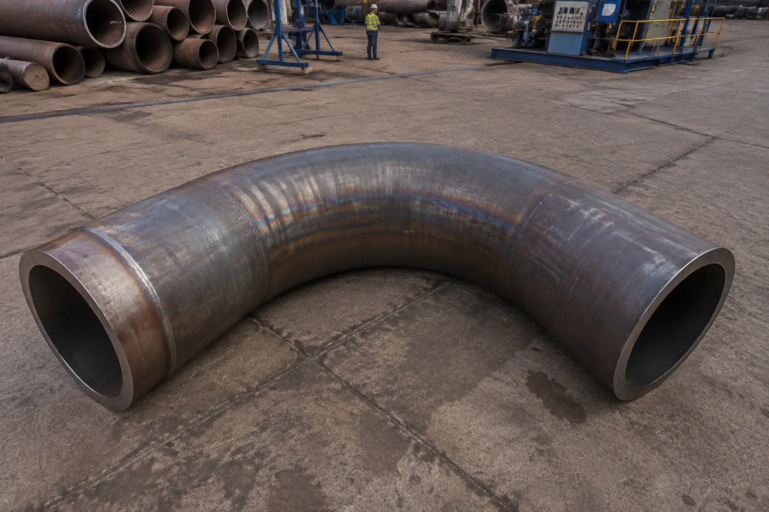
You have probably lost entire afternoons to elbow counts. Not the satisfying kind — the slow, paper-chase kind, where a spool drawing arrives at 4:40 on a Friday with twelve elbows crammed into a forty-foot run between a reactor nozzle and the next rack, and you find yourself tallying weld procedures, radiographic shots, and PWHT hours before the coffee has had a chance to settle. The induction bend sits at the other end of that arithmetic: one continuous piece of pipe, two field girth welds gone, a smoother path for the medium inside. Whether that swap earns its keep depends on what the line is actually carrying — pressure, diameter, fluid — and on the inspection regime that follows the welds.
Mechanical Integrity and Fluid Dynamics: Why Radius Matters
Every change of direction costs you something. In a process pipe, what you lose to a sharp turn is the same thing you lose to friction at the wall — pressure head, pumping energy, and a quiet bit of your operating margin. The standard ASME B16.9 welded elbow arrives in two familiar geometries: 1D short radius, which swings hard through ninety degrees in a footprint roughly equal to the pipe diameter, and 1.5D long radius, which softens that arc a little. Both are reasonable, both are economical for the bulk of utility and low-pressure service, and both are sitting on a distributor's shelf.
Induction bending works the other way around. Rather than buying a fitting, you take a length of straight pipe and bend it in place, with a high-frequency induction coil heating a narrow longitudinal band — typically 25 mm to 50 mm wide — to between 850 °C and 1000 °C while a thrust arm pushes the pipe through the arc. The result is a bend whose radius is no longer constrained by a catalogue page. Standard practice lands at 5D for piggable pipelines, but the process can produce radii anywhere from 3D up to 40D depending on what the line and the medium actually need.
The larger the radius, the quieter the fluid — and the easier the line is to walk with a pig, an MFL tool, or a geometry gauge two decades from now.
That flexibility does real work on the engineering. A gradual change of direction produces lower pressure drop and lower frictional losses than a sharp elbow, because the flow does not have to detach from the inside wall and reattach on the far side of the fitting. In critical service — large-diameter gas, slurry, or any line you plan to inspect regularly with intelligent pigging — the radius is not cosmetic. It is the difference between a pipeline that runs clean and one that traps solids, corrodes under deposits, and forces you back into dig campaigns years before the next planned turnaround.
The other side of the radius question is geometry. A tight plot plan, a congested rack, or a short spool between two fixed nozzles may simply not allow a 5D bend to land where it needs to. Induction bending does not solve layout problems; it solves material and weld-count problems. If the physical space demands a 1.5D turn, the standard long-radius elbow remains the rational choice — regardless of how clean the alternative looks on paper.
The Economics of Girth Welds and NDT Requirements
The price tag most people associate with a welded elbow is misleading. The fitting itself is cheap. What compounds is everything attached to it: the butt-weld preparation on each end, the qualified weld procedure, the welder, the purge gas on stainless or alloy service, the visual and dimensional inspection, and — for high-pressure or critical fluid service — the radiographic or ultrasonic examination that follows. Each girth weld is its own small project.
A single induction bend, by contrast, arrives from the bending facility with two factory-attached pup pieces ready to be welded into the line. Replace one welded elbow with one induction bend and you have eliminated two girth welds — one at each end of the fitting. On a long run that originally called for a dozen elbows, the savings compound quickly, and they land in places that often get overlooked during budget review.
Every elbow you remove from the run is two girth welds you never have to weld, radiograph, or hope passes the next turnaround inspection.
The arithmetic shifts most decisively where the code does. ASME B31.3 and similar process piping standards tighten NDT requirements as service severity climbs — higher pressure, more corrosive or hazardous fluid, sour service. Once 100% radiographic examination of girth welds is mandatory, every avoided weld is not just a labour saving but a meaningful reduction in radiography time, exposure, and the documentation burden that follows. For owners and EPCs managing both schedule and dose-budget on a refinery or gas-plant build, that is real money.
There are limits to the calculation. Off-the-shelf elbows from a distributor remain cheaper than a custom-radius induction bend for small-diameter, low-pressure utility lines where the NDT regime is light. The crossover sits somewhere around NPS 24 — above that, the weld-count and NDT savings tend to dominate the cost of the bend itself; below it, the catalogue fitting usually wins. As a working rule, induction bending earns its place on large-diameter, high-pressure, or critical-service runs, and rarely on small-bore utility drops.
Managing Extrados Wall Thinning Under ASME B31.3
Bending pipe — cold or hot — does something predictable. It stretches the metal on the outside of the arc and compresses it on the inside. The outside surface, the extrados, thins. For a standard cold bend, that thinning is modest and well known. For induction bending, where the wall sees sustained elevated temperature and significant plastic strain, the thinning can reach 10% to 15% on the extrados, with corresponding thickening on the intrados.
This is not a defect. It is a design input that the code already accounts for. ASME B31.3 Section 304.2 provides the calculation for required wall thickness after forming, and the designer is expected to start the wall selection thick enough that the thinned extrados still meets the code-required minimum at every point along the bend. The trap that catches people is treating the bend as if it were a piece of straight pipe with the original nominal wall — that assumption can quietly push a high-pressure line below its required thickness at the worst possible location, and the failure mode it sets up is the kind that does not announce itself until a hydrostatic test, or worse, until several years of service.
Wall thinning at the extrados is not a defect — it is a line item the code already has a calculator for, if you remember to open it before the spool is rolled.
In practice, the verification step looks like this. The bender provides measured wall-thickness data along the bend, with the minimum at the extrados of the point of tangency. The piping stress engineer folds that value into the flexibility and pressure-design checks, and the QA package documents the as-bent thickness against the required minimum. Where the as-bent value drops below the requirement, the answer is to up the starting wall on the next order — not to grind, weld-rebuild, or negotiate with the inspector. The discipline is upstream.
There is a related inspection point worth noting. The heat-affected band that travels through the bend during induction heating is narrow, but the metallurgy inside that band has seen austenitising temperatures and rapid cooling. For carbon and low-alloy steels in benign service, this is rarely a problem. For sour service under NACE MR0175, for low-temperature carbon steels, or for austenitic stainless steels that have to meet corrosion-test criteria, post-bend heat treatment or solution annealing may be mandatory — and that requirement, along with the cost of the heat-treatment furnace and the queue time, needs to sit in the cost comparison from the very first quotation.
Thermal Processing and Material Metallurgy in Induction Bending
The heating band itself is the heart of the process. A high-frequency induction coil moves with the pipe (or the pipe moves through a stationary coil) and raises a narrow longitudinal band to austenitising temperature in a matter of seconds. An internally cooled shoe supports the bore against collapse; an external shoe controls the radius. Behind the coil, an air or water quench drops the temperature rapidly, locking in the bend geometry. The work is governed by ASME B16.49 and ISO 15590-1, which set out the manufacturing tolerances, mechanical property requirements, and inspection expectations for induction bends used in pipeline and process service.
What is happening, in metallurgical terms, is a controlled thermomechanical cycle. Austenite forms, grain refinement occurs, and depending on the cooling rate you can land anywhere from a fine-grained ferrite-pearlite in carbon steel to a potentially sensitised grain boundary in an austenitic stainless if the cooling profile is wrong. The bender's job is to make that cycle reproducible run after run, with the same heat input and the same travel speed. That reproducibility is what makes the process suitable for code work — the metallurgy is traceable to a procedure qualification record rather than to the variable hand of a fabricator.
Two practical implications follow for the engineer. First, the procedure qualification record matters. A bender who cannot document coil frequency, travel speed, temperature profile, and post-bend mechanical properties is a bender you do not want on a critical-service line, no matter how attractive the quotation looks. Second, post-bend heat treatment is not optional for every material. Low-alloy steels in heavy walls, certain Cr-Mo grades, and duplex or super-duplex stainless steels often need PBHT or a solution anneal to restore impact toughness or to redissolve embrittling phases. The cost of that step, including furnace capacity and queue time, must be visible in the comparison before the purchase order is cut.
Strategic Selection: When Continuous Bends Earn Their Place
The honest answer to whether induction bending is worth the investment is that it depends on the line, and that the dependence is concrete rather than philosophical. The general shape of the decision is straightforward, and the trade-offs line up along a few predictable axes.
A continuous induction bend tends to make sense when several of the following are true at once: the line is large-diameter — broadly NPS 24 and up; the service is high-pressure, critical, or otherwise bound to a demanding NDT regime; the route allows a 5D or longer radius without redesigning the layout; and the line is intended to be pigged at some point in its life. Under those conditions, the elimination of two girth welds per directional change, the reduction in pressure drop, and the piggability tend to dominate the higher unit cost of the bend.
A standard welded elbow remains the right answer in the opposite case: small diameter, low-to-moderate pressure, tight geometry that demands a 1D or 1.5D turn, or a service where the inspection regime is light. In those conditions, the catalogue fitting is cheaper, immediately available, and does not require a custom fabrication schedule.
A compact way to frame the choice:
| Parameter | Welded elbow (ASME B16.9) | Continuous induction bend |
|---|---|---|
| Standard radius | 1D (short), 1.5D (long) | 3D up to 40D, typically 5D for piggable lines |
| Girth welds per direction change | 2 (one at each end of the fitting) | 0 at the bend itself; 2 only at the pup-to-line joints |
| Typical extrados wall thinning | Minimal for standard fittings | 10% to 15%; verified under ASME B31.3 §304.2 |
| Pressure drop and piggability | Higher frictional loss; short radius not piggable | Lower pressure drop; piggable from 5D upward |
| Diameter sweet spot | Strong economics at NPS ≤ 24 | Most cost-effective at NPS 24 and above |
| NDT/RT impact per elbow | Full butt-weld RT or UT on high-pressure service | Limited to the pup-to-line joints |
| Lead time | Stock item, days | Custom fabrication, weeks |
The table is not a verdict on every spool. It is a way of seeing which factors actually move money in your project. If the items that matter are dominated by the left column — small diameter, modest pressure, short lead time — the welded elbow wins. If they are dominated by the right column — large diameter, high pressure, long-term piggability, severe NDT regime — the induction bend earns its keep.
Where the Decision Actually Lands
The interesting projects are rarely a clean win for either option. Most process pipe racks contain both: long, critical, large-diameter lines where a continuous bend pays for itself in saved welds and inspection hours, and dense utility drops where a 1.5D elbow is the only sensible answer given the geometry and the budget. The work is to recognise which is which before the isometric drawings are issued for fabrication.
What tilts the decision most often is not the cost of the bend itself but the cost of the welds it replaces — and the inspection regime that follows them. On a high-pressure gas line or a critical hydrocarbon service under tight NDT requirements, every avoided girth weld is a real saving in welder hours, radiographic exposure, and the small but cumulative risk of a defect that has to be excavated and repaired. On a utility air or water line in non-critical service, that same saving does not exist, and the catalogue elbow is the right call.
The induction bend is a tool, not a philosophy. It works where the geometry allows it, where the service demands it, and where the inspection regime makes the weld count expensive enough to remove. It does not work where the radius is constrained by the plot plan, where the diameter is small, or where the cost of post-bend heat treatment would erase the savings before the first weld is laid. Read the line, read the code, count the welds you are about to commit to — and the answer usually settles on its own.