Why Does Clad Plate Welding Follow a Strict Pass Order?
Clad plate welding is not a place for improvisation disguised as craftsmanship. The corrosion-resistant layer may be thin compared with the carbon-steel base, but it is doing a job far beyond…
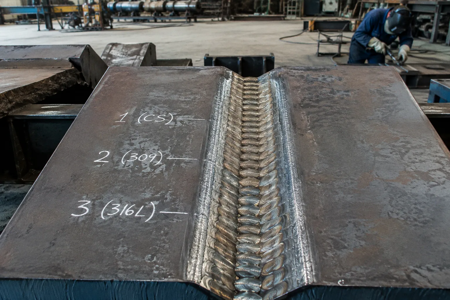
Clad plate welding is not a place for improvisation disguised as craftsmanship. The corrosion-resistant layer may be thin compared with the carbon-steel base, but it is doing a job far beyond decoration: it protects the pressure boundary from the process medium. If the welding sequence mixes those two materials carelessly, the result can be a joint that looks complete while losing the very corrosion resistance the cladding was installed to provide.
The standard clad plate welding sequence for a pressure vessel is therefore deliberately unglamorous:
1. Weld and fully fuse the carbon or low-alloy base metal.
2. Apply a compatible high-alloy transition layer.
3. Restore the corrosion-resistant cladding with the final overlay passes.
That order controls dilution, limits cracking risk, and gives inspectors a weld they can evaluate without relying on optimism. ASME Section VIII UCL-31 reflects the same principle: the base material fusion must be secured before the corrosion-resistant cladding is restored.
The cladding is not the structural shortcut. It is the corrosion barrier, and the welding sequence must protect both jobs.
The mechanics of dilution: why the base metal must come first
Clad plate is built from two different metallurgical responsibilities.
The base plate—usually carbon steel or low-alloy steel—carries the main mechanical load. It forms the pressure boundary and provides the strength required by the vessel design. The cladding, often stainless steel or another corrosion-resistant alloy, faces the process side and protects the base material from corrosive, reactive, or otherwise aggressive service conditions.
Those layers are bonded together during plate production, but the weld joint still has to be rebuilt locally. Once the bevel is prepared, the welder is not simply joining one uniform material. The joint contains a base-metal side, a cladding side, and a region where their chemistry can interact.
That interaction is dilution.
When filler metal mixes with the molten parent metal, the final weld chemistry is not determined by the electrode alone. Carbon steel, low-alloy steel, stainless cladding, and filler metal all contribute to the weld pool. The proportions vary with joint geometry, heat input, arc position, welding process, and deposition technique.
This is why a filler metal that is appropriate for restoring stainless cladding may be entirely unsuitable for the first structural passes. It may not provide the required base-metal properties. Conversely, a conventional carbon-steel filler can create a weld deposit that is mechanically adequate but chemically wrong for the corrosion-resistant surface.
The sequence keeps those problems from arriving all at once.
First pass: secure the structural fusion
The base metal is welded first. The objective is full fusion of the carbon or low-alloy portion of the joint, with the weld procedure qualified for the actual material combination, thickness, joint design, position, and service requirements.
At this stage, the weld is concerned primarily with structural continuity. The base-metal weld must penetrate and fuse properly without relying on the cladding to make up for an incomplete root or poorly controlled sidewall.
This is not merely a convenient workshop habit. ASME Section VIII UCL-31 requires the base material fusion to be completed before corrosion-resistant cladding is restored. The logic is straightforward: the pressure-bearing weld must be sound before the corrosion barrier is put back over it.
If the cladding were welded first, the later base-metal passes could melt into that deposit and contaminate it. The final surface might still appear stainless and continuous, but the weld chemistry could be pushed outside the intended range. That can undermine corrosion performance and increase the risk of cracking.
Second pass: absorb the chemical mismatch
The transition layer sits between the base-metal weld and the final corrosion-resistant overlay. Its job is to manage the abrupt change in chemistry.
High-alloy transition fillers such as E309 are commonly selected because their composition can tolerate a degree of dilution from the carbon-steel side while retaining a suitable metallurgical bridge toward the stainless cladding. Typical transition alloys referenced for this service include compositions around 25% chromium and 13% nickel, or around 25% chromium and 20% nickel.
The point is not that E309 is a universal answer. It is that a transition alloy is selected for a defined dilution problem. The correct material still depends on the qualified welding procedure, the base material, the cladding alloy, the design, and the applicable construction requirements. E309, E309L, and related consumables are not interchangeable by corporate decree just because the names look familiar.
Third pass: restore the corrosion barrier
Only after the base-metal weld and transition layer are in place should the corrosion-resistant cladding be restored. A filler such as E316L may be used where the cladding system and qualified procedure call for it.
The final overlay must restore the corrosion-resistant surface across the joint. It should not be treated as a cosmetic cap pass whose only purpose is to make the weld look like the plate around it. It is part of the service-facing barrier.
That distinction matters in pressure vessels because a weld can satisfy a visual inspection and still have a poorly controlled corrosion-resistant layer. The surface may contain excessive dilution, local chemistry that does not match the intended cladding, insufficient overlay thickness, or defects that become significant only after exposure to the process medium.
Joint preparation: strip the cladding instead of contaminating it
The clad steel weld overlay procedure begins before the arc is struck. Joint preparation determines whether the welder can control the boundary between the two materials or is forced to melt them together blindly.
For the bevel zone, mechanical stripping of the cladding is preferred. The corrosion-resistant layer is removed from the joint preparation area so the base metal can be welded directly and cleanly. Mechanical removal also helps prevent cross-contamination from cutting tools or from uncontrolled melting of the cladding into the structural weld.
This is one of those details that can be dismissed as workshop housekeeping until it becomes a repair report. If the cladding remains in the bevel where it should have been removed, the first weld passes may pick up stainless material prematurely. The resulting dilution becomes harder to predict. The welder is then trying to recover a qualified weld chemistry from a joint that was badly defined at the start.
The bevel is not just a groove. It is a metallurgical boundary.
A controlled preparation typically addresses several practical points:
- The cladding is stripped from the joint bevel zone by a method that avoids unnecessary contamination.
- The base-metal groove is prepared to provide reliable access and fusion.
- The remaining cladding edge is clearly defined so the transition layer can be placed deliberately.
- Surface contamination, oxides, grease, and loose material are removed before welding.
- The prepared geometry matches the qualified welding procedure rather than an informal shop preference.
The cladding removal must also be deep enough to expose sound base metal where the structural weld is required. At the same time, it should not become an excuse to remove a large, uncontrolled area that later demands excessive overlay restoration. More excavation means more deposited alloy, more heat, more distortion, and more opportunity for defects. The sensible approach is controlled preparation, not enthusiastic gouging.
Why cross-contamination matters
Stainless and carbon-steel fabrication can share a workshop, but they should not share careless habits. Tools, abrasives, wire brushes, and handling practices can transfer contaminants to the corrosion-resistant surface. The joint preparation method therefore matters both for weld chemistry and for surface condition.
Mechanical stripping is preferred in the cited practice because it creates a clear separation between the base-metal weld zone and the cladding that will later be restored. It also avoids treating the original cladding as filler metal by melting it into the base weld.
That is the central point: the existing cladding is not a controlled consumable. Its chemistry and dilution are not being managed in the same way as a selected electrode or wire. Letting it enter the structural weld pool is a poor substitute for procedure control.
The transition layer is not a decorative middle coat
The base metal to cladding transition weld is where the fabrication team earns its keep. The layer is thin in visual terms but important in metallurgical terms. It must accommodate the difference between the carbon-steel weld and the stainless or high-alloy restoration layer without creating a brittle or crack-sensitive region.
A transition filler such as E309 is selected because its higher chromium and nickel content provides tolerance for dilution from the base-metal side. The exact consumable and technique still belong to the qualified welding procedure. No responsible fabricator should choose a filler merely because it is broadly described as suitable for stainless-to-carbon-steel work.
The practical questions are more specific:
- What is the base-metal grade?
- What is the cladding alloy and thickness?
- How much cladding was removed?
- What welding process and polarity are specified?
- What heat input range is permitted?
- Is preheat required?
- Is post-weld heat treatment required for the base material or vessel construction?
- What acceptance criteria apply to the transition and overlay?
- How will the restored cladding be examined?
The research basis identifies a minimum clad thickness benchmark of 7/64 inch, or 0.109 inch. That figure is useful as an industry reference, but it does not replace the design documents or the qualified procedure for a particular vessel. The required restoration thickness belongs to the actual cladding system and engineering requirements.
Dilution control is a sequence problem and a technique problem
Changing filler metal does not magically solve dilution. The welder still has to control the amount of base metal melted into each layer.
That involves practical control of:
- Arc placement, especially near the exposed cladding edge.
- Bead size and overlap.
- Heat input and interpass temperature.
- The number of transition passes.
- Cleaning between passes.
- The width and thickness of the final overlay.
- The order in which local repairs or attachments are completed.
The transition layer must be thick and continuous enough to separate the base-metal chemistry from the final corrosion-resistant layer. It must also avoid creating excessive heat accumulation in the plate, particularly where the joint is long, thick, restrained, or connected to other welds.
There is no useful universal instruction such as weld slowly or keep the heat low. Slow welding can increase heat input if it is not balanced by current and travel speed. Low current can produce inadequate fusion. The useful control comes from the qualified WPS, actual joint geometry, and disciplined execution—not from slogans printed on a wall.
A transition layer is successful when it manages chemistry and stress, not when it merely adds another visible line to the weld.
E309, E309L, and procedure discipline
The E309 family is commonly associated with transition work because its alloy balance is intended to handle dilution and provide a bridge between dissimilar materials. Lower-carbon variants such as E309L may be specified in some procedures, but the correct choice is not determined by the label alone.
A pressure-vessel shop should be able to explain why a particular consumable was selected and where it is permitted in the sequence. That explanation should be traceable to the WPS and supporting qualification records.
The same applies to heat treatment. Specific preheat requirements, interpass limits, and PWHT soak times cannot be safely invented from a generic description of clad plate. They depend on the proprietary alloy combination, base material, thickness, restraint, code requirements, and qualified procedure. Where those details are not established, the answer is not confident improvisation. It is a procedure review.
Restoring corrosion resistance: the final overlay has a real thickness requirement
Once the transition layer has been deposited, the cladding restoration passes rebuild the process-facing surface. The goal is to provide a continuous corrosion-resistant layer with adequate thickness and sound fusion to the underlying transition metal.
The overlay cannot be thinner simply because the area is difficult to reach or because the final machining allowance was misunderstood. The cited fabrication benchmarks require the restored weld overlay to be at least equal to the original cladding thickness over areas where the cladding was removed. The maximum permitted restoration thickness is identified as up to twice the original clad thickness, subject to the governing requirements and procedure.
That range prevents two opposite errors:
1. Underbuilding the corrosion barrier.
2. Depositing excessive material that creates unnecessary heat, distortion, machining, and inspection problems.
The final overlay also has to blend into the surrounding cladding. A sharp step, undercut, overlap, crater, or isolated low area can create a practical corrosion site even if the average thickness looks acceptable.
The restoration work may involve several passes rather than one large deposit. Multiple controlled passes allow better management of bead shape, dilution, interpass temperature, and local defects. The exact pass arrangement is procedure-specific, but the principle is stable: build the corrosion layer deliberately, then verify it.
What should be verified after overlay welding?
The inspection plan depends on the construction code, vessel design, material combination, and qualified documentation. Still, the restoration stage commonly raises several questions that should be answered before the component is released:
- Is the overlay continuous across the entire stripped area?
- Does its thickness meet the specified minimum?
- Has the transition boundary remained covered?
- Are there cracks, lack of fusion, porosity, undercut, overlap, or other surface defects?
- Has the surface been finished without reducing the overlay below its required thickness?
- Does the examination method cover the areas most likely to contain dilution or incomplete fusion?
- Are any required corrosion-resistance or surface examinations complete?
The final surface is where the process medium will eventually make its complaint. It tends to be less diplomatic than a drawing review.
Internal attachments: why high-shear connections need a separate approach
Clad restoration becomes more complicated around major internal attachments. Supports, baffles, lifting features, distributors, and other components may transfer significant shear loads into the vessel wall. In those areas, welding directly onto the cladding can create a structural problem because the cladding is not intended to replace the base steel as the primary load path.
For major internal pressure-vessel attachments subjected to high shear loads, the internal cladding is stripped from the attachment weld zone. The attachment is welded directly to the base steel, and the removed corrosion-resistant layer is restored afterward with weld overlay.
This creates a sequence within the larger sequence:
1. Remove the cladding from the attachment footprint and the required surrounding area.
2. Weld the attachment to the exposed base steel using the qualified structural procedure.
3. Restore the cladding around and over the affected region with the specified overlay.
4. Confirm that the restored surface and attachment geometry meet the design and examination requirements.
The cited guidance identifies a minimum clearance of 20 mm between the toe of the attachment-to-base weld and the cladding edge. That clearance gives the structural weld enough separation from the cladding boundary to control fusion and avoid an uncontrolled transition at the weld toe.
The point is not to create a universal layout rule for every attachment. It is to prevent the attachment weld from straddling an undefined metallurgical boundary. If the structural weld terminates directly at the edge of the cladding without adequate control, the fabrication team inherits a difficult combination of stress concentration, dilution, access limitations, and corrosion-restoration work.
Why welding directly to the cladding is often the wrong shortcut
It is tempting to leave the cladding in place and weld the attachment through it. The fabrication sequence looks shorter. The drawing may appear cleaner. The schedule spreadsheet gets to feel important for several minutes.
But the shortcut can compromise both functions of the joint. The cladding may not provide the required structural connection for the attachment, while the attachment weld may damage the corrosion barrier or produce an uncontrolled mixture of materials.
Stripping the cladding, making the structural connection to the base steel, and restoring the corrosion layer afterward is more work. It is also a clearer engineering solution. The base metal carries the load. The overlay restores the service surface. Each material is asked to do its intended job.
Where fabrication teams usually lose control
The most serious problems in clad steel welding are rarely caused by a mysterious metallurgical event. They tend to start with ordinary production pressure:
- The bevel is prepared without clearly removing the cladding from the structural weld zone.
- The stainless restoration filler is used for a base-metal pass because it is already at the welding station.
- The transition layer is omitted or applied too thinly.
- The operator follows a generic stainless-steel procedure instead of the qualified procedure for the clad combination.
- The overlay is machined aggressively and ends up below the required thickness.
- An attachment is welded onto the cladding because stripping and restoration were not planned.
- Inspection is treated as a final formality rather than as part of the restoration sequence.
These are not all equal failures, but they share one cause: the joint is treated as a single material after fabrication has already created a two-material problem.
A useful production review should therefore focus on the sequence rather than on paperwork volume. Before welding begins, the team should be able to identify:
- Where the cladding is removed.
- Which passes belong to the base-metal weld.
- Which consumable is used for the transition layer.
- Which consumable restores the final cladding.
- How overlay thickness will be measured.
- How internal attachments interact with the stripped and restored areas.
- What inspections are required at each stage.
- Which heat-treatment requirements apply to the specific material combination.
This is not bureaucracy for its own sake. It is how the shop prevents a corrosion-resistant pressure boundary from becoming a chemistry experiment.
The direct answer
Why does clad plate welding follow a strict pass order?
Because each layer has a different job, and welding them in the wrong order allows the materials to contaminate one another before their functions are secured.
The base metal must be welded first so the pressure-bearing joint achieves full fusion. The transition layer comes next to absorb dilution from the carbon or low-alloy steel and provide a controlled metallurgical bridge. The final high-alloy overlay is deposited last to restore corrosion resistance without exposing it to uncontrolled base-metal dilution.
Joint preparation reinforces the same logic: strip the cladding from the bevel zone, weld the structural material directly, then rebuild the corrosion barrier. Around high-load internal attachments, weld to the base steel rather than asking the cladding to carry structural shear, and restore the removed layer afterward.
There is no clever shortcut here. The sequence is the control system. Ignore it, and the weld may still look finished while the pressure boundary has lost either structural reliability, corrosion resistance, or both. In pressure-vessel fabrication, that is a poor definition of done.