3D Laser Scanning for Steel Frame Virtual Fit-Up
A steel frame can be dimensionally correct on paper and still refuse to assemble cleanly on site.
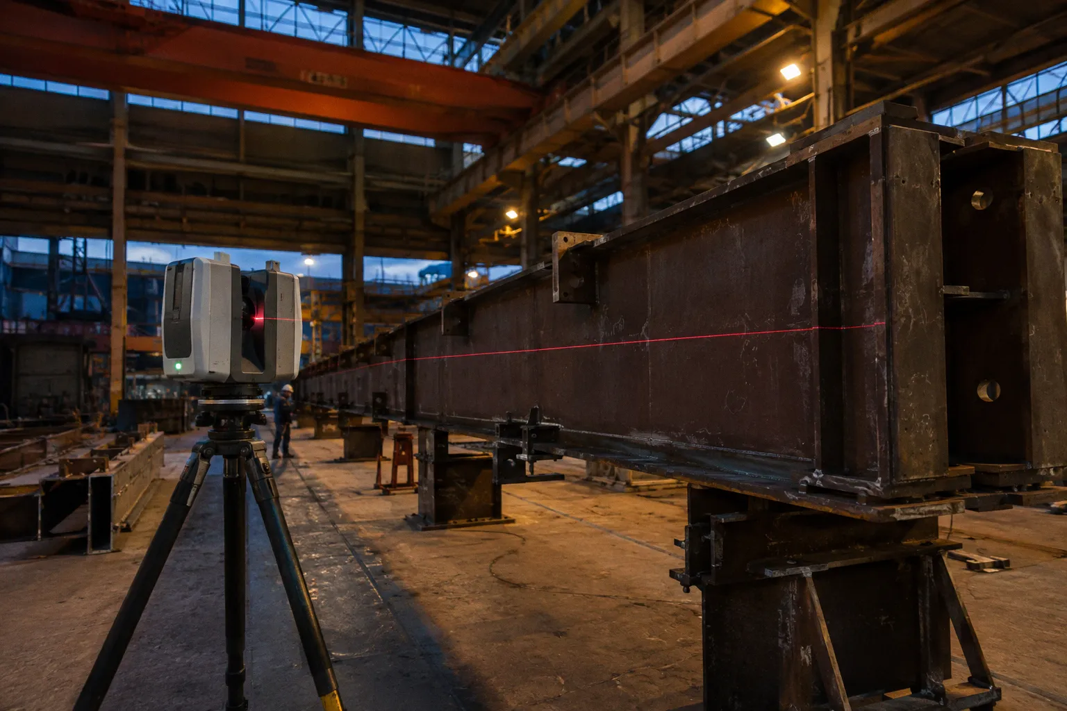
A connection plate may sit a few millimeters away from its intended position, a bolt pattern may drift, or two members may arrive with a geometric clash that was invisible in the drawing set. By the time the problem becomes visible during erection, the cost is no longer limited to fabrication: transport, crane time, crews, schedule, and site access are already involved.
3D laser scanning for steel structure virtual fit-up moves that moment of discovery back into the workshop. Instead of relying only on manual measurements or a physical trial assembly, the fabricator captures the assembled steel as a dense three-dimensional point cloud, aligns it with the structural BIM model, and studies the difference before the frame leaves the shop.
The method does not replace welding inspection, ultrasonic testing, radiography, or every physical fit-up check. It answers a different question — whether the fabricated geometry corresponds to the intended digital geometry closely enough for the next stage of work.
What virtual fit-up actually checks
Virtual fit-up is the digital equivalent of assembling structural members before transport, only with the assembly represented as measured data rather than as a second full-scale construction operation.
A laser scanner records millions of points per second. Each point carries an X, Y, and Z coordinate, and together these coordinates form a point cloud — a measured representation of the fabricated members, plates, stiffeners, holes, weld build-up, and surrounding geometry that the scanner can see. The point cloud can then be aligned with the structural BIM model, including models created in platforms such as Tekla Structures or Revit.
The comparison is not merely a visual overlay. A properly organized workflow can produce a three-dimensional color-difference map showing where the physical steel departs from the modeled position. Depending on the project requirements, the inspection team can examine:
- overall member position and orientation;
- connection plate location and inclination;
- bolt-hole and bolt-pattern alignment;
- flange and web geometry;
- clearances between intersecting members;
- local clashes at stiffeners, brackets, and gussets;
- accumulated deviation across a frame or subassembly;
- dimensional relationships that will affect transport or site erection.
This distinction matters. A component can look acceptable when measured from one reference point and still carry an accumulated error along its length. A column base may be correctly positioned while its upper connection has rotated slightly. A manual check might confirm both points separately; a point-cloud comparison can reveal the spatial relationship between them.
Virtual fit-up is not about making steel look precise on a screen — it is about settling geometric uncertainty before that uncertainty reaches the construction site.
The most useful result is therefore not a colorful scan by itself, but a decision: release the assembly, correct it, measure again, or escalate the deviation for engineering review.
From point cloud to digital twin
The phrase “digital twin” is often used too broadly. In this context, it means that the fabricated steel has been captured as a measured spatial dataset that can be related directly to its intended BIM geometry. The scan does not create an abstract image of the frame. It records the physical frame in a coordinate system that allows meaningful comparison.
That comparison begins with registration and alignment. The scan data may contain several positions of the same assembly, overlapping scans, temporary supports, floor features, and surrounding equipment. These datasets must be brought into a common coordinate framework before deviation can be interpreted. If alignment is poor, the resulting map may display registration error as if it were fabrication error.
For this reason, the workflow needs a controlled reference strategy. The inspection team must establish which points, planes, grids, or known features define the comparison, and whether the question concerns absolute position or the internal geometry of the assembly. A frame can be shifted as a whole relative to the shop floor while remaining internally accurate; those are different findings and should not be mixed.
A practical comparison sequence
A useful virtual trial assembly usually follows a sequence like this:
1. Prepare the assembly and the model.
The steel members, connection details, and relevant reference geometry are identified, while the BIM model is checked for the version and coordinate system that govern fabrication.
2. Capture the physical steel from sufficient viewpoints.
Scanner position, line of sight, surface access, and occlusion all influence the completeness of the point cloud. Connection zones hidden behind plates or members may require additional scan positions.
3. Register and clean the scan data.
Overlapping scans are combined, irrelevant surroundings are filtered, and the inspection team confirms that the resulting cloud is stable enough for comparison.
4. Align the point cloud with the BIM model.
The chosen datum and registration method should reflect the purpose of the check — overall erection geometry, connection fit, bolt pattern, or another defined requirement.
5. Generate deviation maps and targeted measurements.
The color map helps locate patterns of deviation, but the final assessment should also use explicit dimensions, tolerances, and connection-specific measurements.
6. Classify the result and preserve the record.
The output should show which elements are within the agreed range, which require correction, and which need engineering disposition before release.
This is where dimensional tolerance checking with a 3D scan becomes more than a photograph with coordinates. The scan provides evidence, but the project still needs a tolerance logic. Without an agreed acceptance range, a deviation map can be visually impressive and operationally vague.
LOA30, LOA40, and the meaning of millimeter-level accuracy
Laser scanning in steel fabrication is commonly discussed in relation to Level of Accuracy, or LOA. The relevant question is not whether the scanner has a high nominal specification in isolation. It is whether the complete measurement chain — scanner, registration, target setup, environment, model, and interpretation — supports the tolerance required for the assembly.
For structural fit-up work, reported accuracy commonly operates at millimeter level. Tight connection and fit-up verification may work within approximately ±1 mm to ±5 mm, depending on the task and the defined LOA. High-precision tie-in and connection checks may target approximately ±1 mm to ±3 mm, while standard detailed design and prefabrication work may use a range closer to ±5 mm. Early feasibility layouts can tolerate a broader range, around ±10–15 mm, because they answer a different question.
These ranges should not be treated as universal pass-fail rules. A ±5 mm deviation may be insignificant for an early layout and unacceptable at a tightly controlled connection. The same numeric difference can carry different consequences depending on bolt-hole clearance, plate thickness, member length, erection sequence, and the way the structure transfers load.
Accuracy is a system property
Several conditions can soften or distort the measurement if they are not controlled:
- the scanner may not see the full surface of a connection;
- reflective, dark, dusty, or obstructed surfaces can reduce usable data;
- long members can introduce alignment questions across their full length;
- outdoor scanning brings environmental variables, including temperature effects on large steel members;
- temporary supports may shift the assembly from its intended fit-up condition;
- the BIM model may not reflect the latest approved fabrication revision;
- a dense point cloud can still be interpreted incorrectly if the reference system is wrong.
The last point is easy to overlook. More points do not automatically mean better decisions. A point cloud with excellent local density but weak registration can create false confidence. Conversely, a scan that is properly planned for the connection zones may support a reliable acceptance decision without capturing every square centimeter of the workshop.
For a steel frame, the inspection plan should therefore define the required accuracy before scanning begins. The question is not simply, “Can we scan this?” It is, “What must this scan prove, relative to which datum, and at what tolerance?”
Choosing between phase-based and time-of-flight scanners
Industrial reality-capture scanners used for structural steel generally fall into two broad groups: phase-based scanners and time-of-flight scanners. The choice is shaped by range, density, speed, access, and the scale of the assembly.
| Parameter | Phase-based scanner | Time-of-flight scanner |
|---|---|---|
| Typical strength | Rapid, high-density capture at shorter ranges | Longer-range capture across yards and large structures |
| Best environment | Workshop bays, fabrication areas, detailed assemblies | Outdoor yards, large frames, long sightlines |
| Point density | Suited to dense local documentation | Suited to broad coverage over greater distances |
| Main benefit | Detailed connection and fit-up information | Flexible coverage of large or widely spaced geometry |
| Main constraint | Less suitable when the assembly is very large or far from the scanner | May require more planning when fine local detail is critical |
| Fit-up role | Connection plates, bolt zones, local assembly geometry | Overall frame position, large modules, outdoor pre-assembly |
The categories are not a substitute for a project-specific survey plan. A phase-based scanner may be useful for a dense connection area, while a time-of-flight system may settle the position of a large module in an outdoor fabrication yard. In some projects, both kinds of data may contribute to the inspection, provided their coordinate systems and accuracy characteristics are managed coherently.
The physical setup matters as much as the scanner class. A line of sight that seems open from the operator’s position may still leave the rear face of a plate hidden. Scanning from several stations can improve coverage, but only if the stations can be registered without introducing avoidable error. The aim is not to collect the largest file. It is to capture the surfaces and reference features that control the fit-up decision.
Automated deviation mapping for complex assemblies
A structural BIM model and a point cloud can be compared in a way that makes patterns visible quickly. Color-difference maps are especially useful for locating areas that deserve a closer look: an entire member leaning in one direction, a plate rotated around its axis, or a cluster of deviations gathered around one weldment.
Automation helps because complex assemblies contain too many relationships for a purely manual review to remain comfortable. It can assist with repetitive measurements, surface-to-surface comparison, extraction of connection coordinates, and reporting of deviations across multiple members.
But automation should soften the workload, not remove judgment. A deviation map does not know whether a temporary lifting lug is part of the approved geometry, whether a support has altered the member’s position, or whether a model element belongs to an earlier design revision. It can show a difference; it cannot independently determine the engineering meaning of every difference.
Reading the pattern, not just the maximum number
A single maximum deviation can be less informative than the shape of the deviation across the assembly.
Consider three simplified patterns:
- Uniform translation: the member has shifted as a whole, while its internal geometry remains consistent. This may point to a setup or datum issue rather than a fabrication defect.
- Progressive drift: one end aligns while the other moves away from the model. This may indicate rotation, accumulated fabrication deviation, or a member that is not resting as intended.
- Localized concentration: most of the assembly aligns, but one plate, stiffener, or connection zone shows a sharp departure. This directs attention toward a local fabrication or attachment issue.
The scan becomes valuable when it supports this kind of reasoning. Instead of asking only whether a part is “in tolerance,” the team can ask where the deviation begins, whether it repeats across related members, and whether the pattern could affect erection, bolt installation, or the next fabrication operation.
For petrochemical steel fabrication, that context is particularly important. Pipe racks, access structures, equipment platforms, and support frames often combine dense connection zones with long members and constrained site sequencing. A geometric issue that appears small in isolation may become disruptive when several modules meet around fixed equipment or pre-installed systems.
Laser scanning for petrochemical steel fabrication can help identify those spatial conflicts before transport, but it does not replace the separate quality controls required for weld integrity, material traceability, coating performance, or pressure-containing equipment.
What scanning can — and cannot — replace
3D scanning is strongest when the problem is geometric. It can compare where the fabricated steel is with where the model says it should be. It can expose misalignment, clash conditions, and dimensional drift across an assembly. It can also preserve a measured record that can be revisited when a question emerges later.
It is not a substitute for non-destructive testing. A scan cannot establish weld soundness in the way ultrasonic inspection or radiographic testing can. It does not confirm the internal condition of a weld, the material grade, heat-treatment history, or coating adhesion. Nor does it eliminate every physical fit-up check, particularly where the project specification requires direct verification or where complex geometry creates occlusions that cannot be resolved from the scan alone.
The boundaries are practical rather than disappointing. A good inspection system assigns each tool the question it can answer reliably:
- 3D laser scanning: Where is the fabricated geometry, and how does it compare with the model?
- Ultrasonic testing: Are there relevant internal discontinuities in the inspected weld or material zone?
- Radiographic testing: Does the radiographic image reveal specified internal conditions in the tested weld?
- Visual and dimensional inspection: Is the visible workmanship and measured geometry acceptable under the project requirements?
- Coating tests: Does the applied coating meet the specified thickness and adhesion requirements?
- Document control: Can the result be connected to the correct drawing, revision, member, and inspection record?
The strength lies in combining these layers without asking one of them to carry the whole quality system.
A point cloud can tell you that two steel members will not meet as designed; it cannot tell you why a weld failed inside the joint.
Rework reduction: where the value becomes visible
The business case for virtual fit-up is usually made in the language of avoided rework. That is reasonable, but the savings do not come from the scan alone. They come from finding a problem while correction is still contained within the fabrication process.
A workshop correction may involve repositioning a plate, modifying a connection, adjusting a member, or returning an assembly to a controlled work area. A site correction can involve cranes, access restrictions, permit coordination, weather exposure, transport disruption, additional crews, and changes to the erection sequence. The geometric deviation may be identical; the operational consequences are not.
Research and industry reporting on reality-capture workflows in steel fabrication describe rework reductions of up to 95% compared with conventional manual measurement and physical pre-assembly methods. That figure should be understood as a reported upper result for particular workflows and conditions, not as a guaranteed outcome for every project. The actual benefit depends on the baseline process, assembly complexity, scan quality, model reliability, response time, and whether the organization is prepared to act on the findings.
The most durable value often appears before a dramatic failure is prevented. A scan can reveal repeated drift in a cutting or welding process, a recurring issue in a connection detail, or a mismatch between the fabrication model and the approved design. Once that pattern settles into the quality record, the team can address the process rather than correcting each isolated member.
Turning scan findings into process control
To make the method part of manufacturing quality rather than a one-time survey, the output should connect with the existing production system:
1. Link each scan to a defined assembly and model revision.
A measurement without identity is difficult to defend later.
2. Separate geometric findings from other inspection results.
Dimensional deviation, weld quality, coating condition, and material documentation should remain traceable as distinct controls.
3. Record the tolerance used for acceptance.
The report should show not only the measured difference but also the criterion against which it was assessed.
4. Feed recurring deviations back to fabrication.
Repeated errors may indicate fixture movement, cutting setup, welding sequence, distortion, or a modeling issue.
5. Rescan after correction where the risk justifies it.
The purpose is to settle the question, not merely to document that a correction was attempted.
6. Preserve the point cloud and report in the project record.
The scan can become useful again during erection, dispute resolution, modification, or later maintenance planning.
This is the point at which 3D laser scanning begins to support a wider ISO 9001 quality-control environment. It can strengthen traceability and evidence, but certification itself does not come from using a scanner. The quality system still depends on controlled procedures, competent personnel, document management, corrective action, and consistent verification.
The limits of a perfectly measured wrong model
The most subtle risk in digital fit-up is not inaccurate scanning. It is accurate scanning compared against the wrong geometry.
A point cloud may align beautifully with a BIM model that has since been superseded. A fabricated member may match the shop drawing but not the latest approved design. A connection may be measured correctly while the intended tolerance has changed through an engineering revision. If the model, drawing, and inspection criteria are not synchronized, the technology can produce a precise answer to the wrong question.
Before the scan reaches the comparison stage, the team should settle:
- which model revision governs;
- which coordinate system and datum apply;
- whether the assembly is measured in its fabricated or supported condition;
- which surfaces and connection features are critical;
- what tolerance applies to each class of deviation;
- who has authority to accept, correct, or escalate a finding.
This is not bureaucratic overhead. It is what allows the measurement to settle rather than expand uncertainty.
A measured path from shop to site
The most convincing use of 3D laser scanning is neither futuristic nor theatrical. It is quiet, repeatable, and close to the work: capture the steel, align the data, understand the deviation, correct what can still be corrected, and release the assembly with a record that others can trust.
For structural steel, the method is especially valuable where geometry accumulates across long members, dense connections, modular assemblies, and constrained erection sequences. LOA30 and LOA40 workflows can support millimeter-level comparison when the scanner, registration, model, environment, and acceptance criteria are treated as one measurement system. Phase-based scanners can settle dense local detail; time-of-flight systems can extend the view across larger yards and structures. Automated deviation maps can make patterns visible, while engineering judgment keeps those patterns grounded in the actual fabrication and erection problem.
The central discipline is simple: use the scan to reduce uncertainty, not to decorate the quality report. When the point cloud is tied to the right model and the right tolerance, virtual fit-up allows the steel to settle into its intended geometry before transport, before the crane is booked, and before a small deviation becomes a site-wide interruption.