Plasma vs Fiber Laser Cutting for Heavy Structural Steel
Every couple of years a new generation of high-wattage fiber lasers lands in the market, and a quiet round of soul-searching begins at heavy structural steel shops. Marketing decks announce the death of plasma.
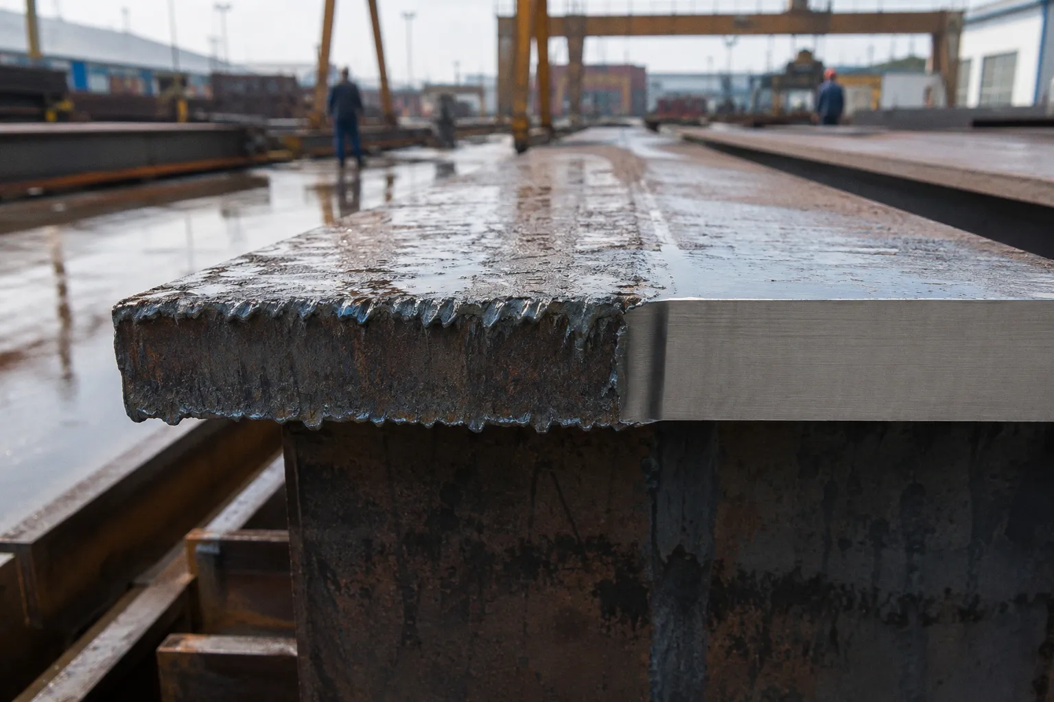
Procurement asks pointed questions about return on investment. The fabricator with twenty years on the shop floor already knows the punchline: plasma is not going anywhere, and pretending otherwise burns budget on parts the laser was never built to cut well.
This is not a sentimental defense of old equipment. It is a working comparison of two thermal cutting processes against the actual conditions of petrochemical and structural steel fabrication — hot-rolled plate, dirty surfaces, thick sections, weld-ready edges. The tradeoffs are measurable. ISO 9013 gives a vocabulary for the precision question. Kerf width and tolerance are not the same thing. Bevel geometry can shape downstream welding economics in ways that matter on the schedule. Each of these deserves more than a one-line mention in a vendor brochure.
Precision and the ISO 9013 Vocabulary
Anyone evaluating cut quality on heavy plate eventually lands on ISO 9013, the international standard that classifies thermal cuts by angularity, drag-line depth (often expressed as mean striation depth), and perpendicularity relative to the plate surface. The standard sorts cuts into five quality ranges — Range 1 is the cleanest, Range 5 is the roughest — and once that scale is understood, the plasma-vs-laser argument gets much less abstract.
Fiber laser cutting typically lands in Range 1 to Range 2. The cut face is nearly perpendicular, the drag lines are shallow, and the bottom edge does not round off much. High-definition plasma systems built for heavy structural work rather than hobby cutting generally hit Range 2 to Range 4. Conventional plasma sits closer to Range 5. When a fabricator quotes Range 1 across the board without naming the process, ask which ISO 9013 component was actually measured — angularity, mean striation depth, or perpendicularity — because the answer tells you whether the laser or plasma claim is marketing or measurement.
The practical consequence shows up at fit-up. A Range 1 laser cut on 12 mm plate goes straight into a welded assembly with minimal grinding and predictable gaps. A Range 3 plasma cut on the same plate may need edge dressing before the fitter can square the joint. That fitter-time cost rarely appears in a per-meter cutting comparison, but it is real, and it scales with every joint in the assembly.
Thickness Capabilities and the 25 mm Threshold
The single most useful number in this comparison is plate thickness, because everything else — tolerance, kerf, surface sensitivity, cutting economics — orbits around it.
Plasma cutting systems handle plate thicknesses from roughly 5 mm up to 160 mm. That span covers nearly the full menu of heavy structural work: gusset plates, base plates, web and flange material for plate girders, stiffener rings for pressure vessels and storage tanks, bracket and saddle plates for pipe racks. Fiber lasers have historically worked the 0.5 mm to 25 mm window — sheet metal, light plate, the kind of work that fills a job shop but rarely anchors a heavy fabrication contract.
The latest generation of ultrahigh-power fiber lasers, in the 20 kW to 50 kW range, is pushing into thicker plate. Real installations now cut 30 mm, 40 mm, and occasionally 50 mm mild steel. They do it at speeds plasma cannot match at the thinner end, and with cut quality plasma cannot match at all. They also cost more per machine, draw more power, and require nitrogen or argon assist gas at flows that shape the operating economics. The threshold question for a heavy structural shop is not whether the new laser can cut 40 mm plate. It is whether the throughput, the surface-preparation burden, and the assist-gas cost justify that capability at the volumes the shop actually runs.
If most of your cuts are above 25 mm and most of your plate arrives rusty, a high-power fiber laser is an expensive way to do what high-definition plasma already does well.
Surface Condition: The Quiet Deciding Factor
This is the section vendor presentations tend to skip past with a single bullet point, and it is often the one that decides whether a job runs on schedule or spends a week in pre-treatment.
Fiber laser cut quality depends on a clean sheet surface. Rust, heavy mill scale, oil, paint, and surface grooves all degrade the cut. The assist gas nozzle sits close to the workpiece, the beam is focused to a small spot, and any contamination at the cut zone causes irregular kerf, dross, and inconsistent edge quality. A fabricator running hot-rolled structural plate — which is most of what arrives at a structural yard — must account for the cleaning step: descaling, shot blasting, or chemical treatment, applied uniformly before the plate touches the laser table.
Plasma cutting tolerates those conditions. Rust, oil patches, paint, and mill scale are routine on heavy structural plate, and a high-definition plasma system cuts through them without a separate pre-treatment line. The cutting energy comes from a high-temperature plasma jet rather than a tightly focused light beam, so the arc itself is less sensitive to surface contamination. For shops receiving hot-rolled plate directly from the mill, that single difference can eliminate an entire work step and the floor space it requires.
There is a corollary worth naming. A laser cell that promises tight tolerances on structural plate without a dedicated surface prep line is selling a fiction. The plate will arrive dirty, the cut quality will drift, and the operator will either slow the machine to compensate or scrap parts. Either outcome erodes the productivity claim that justified the purchase in the first place.
The hidden cost of surface prep
Surface preparation is not free. Shot-blasting a plate to acceptable laser-cut cleanliness takes time, energy, and consumables. A typical blast line running structural plate adds minutes per piece, and those minutes compound across a production run of hundreds of parts. The blast cabinet or line itself occupies floor space that could hold another cutting table or welding station. For a shop whose volume is dominated by thick, dirty plate, the capital and operating cost of a dedicated prep line can easily offset the cutting-speed advantage the laser brings.
Plasma sidesteps that entire equation. The operator loads the plate, programs the cut, and runs. The trade-off is rougher edges and wider kerf — real costs, but costs that are visible and manageable in the downstream workflow rather than hidden in a pre-treatment step that runs whether or not the laser is cutting.
Kerf Width and Tolerance: Two Different Numbers, Often Confused
Kerf is the width of material removed by the cut. Tolerance is how far the actual edge can deviate from the nominal CAD geometry. The two are related but not identical, and the difference matters more in heavy plate than in sheet.
A fiber laser typically removes 0.1 mm to 0.4 mm of material per cut. A plasma system removes 1.5 mm to 4.0 mm. That narrower laser kerf means more parts per plate in nesting, less material waste per cut, and tighter internal features — small holes, narrow slots, fine notches that plasma cannot produce cleanly.
Tolerance tells the other half of the story. Fiber laser cutting holds ±0.03 mm to ±0.1 mm on the dimensions that matter. Plasma cutting, even with high-definition systems, generally holds ±0.5 mm to ±1.0 mm. On a small bracket, that spread is invisible. On a 12-meter-long plate girder flange, it accumulates. A 1 mm tolerance drift per cut, multiplied across multiple cuts that must mate at fit-up, is the kind of number that turns into a Saturday afternoon of grinding on the assembly floor.
| Parameter | Fiber laser | High-definition plasma |
|---|---|---|
| Typical ISO 9013 range | 1–2 | 2–4 |
| Dimensional tolerance | ±0.03 mm to ±0.1 mm | ±0.5 mm to ±1.0 mm |
| Kerf width | 0.1 mm to 0.4 mm | 1.5 mm to 4.0 mm |
| Plate thickness (practical) | 0.5 mm to 25 mm; up to ~50 mm on 30–50 kW systems | 5 mm to 160 mm |
| Natural vertical-edge bevel | Near 0° | 0.5° to 1.5° |
| Surface prep requirement | Clean, scale-free, oil-free | Tolerates rust, oil, mill scale |
The honest reading: pick the process that matches the tightest tolerance on the part, not the tightest tolerance on the data sheet. If the critical feature is a row of bolt holes in 16 mm plate, the laser wins. If the critical feature is a square edge on a 60 mm base plate that lands on a concrete pier, the plasma's looser tolerance is well inside the weld-prep allowance and the field fit-up tolerance.
Bevel Geometry: Where the Welding Economics Live
Heavy structural fabrication rarely ships a square edge. Plate girders, pressure vessel heads, saddle plates, and stiffener rings all need beveled edges for welding — V-grooves, J-grooves, K-grooves when the section gets thick enough. The natural bevel a cutting process produces is the starting point for that weld prep, and the difference between laser and plasma here is structural, not cosmetic.
A high-definition plasma torch, run with proper parameters, produces a vertical-edge bevel of roughly 0.5° to 1.5°. That natural angularity is modest, but on long cuts in thick plate it accumulates into a measurable edge profile. Whether that profile helps or hurts depends on the joint design specified in the welding procedure specification. A consistent, small-angle bevel from plasma can reduce the stock that a separate beveling operation needs to remove, which shortens prep time and limits the number of filler-metal passes on certain joint configurations. But the natural bevel does not replace designed groove geometry — the weld-pass count, filler-metal consumption, and whether back-gouging is required are all determined by the joint design, the groove preparation, and the qualified WPS, not by the cutting process alone.
A fiber laser produces a nearly vertical edge. For welding, that means laser-cut plate typically needs a separate beveling operation — mechanical milling, flame cutting, or a dedicated plasma bevel head — before it can be welded in a heavy section. Some laser cells now integrate a plasma bevel head for exactly this reason, which is a quietly sensible hybrid. The laser handles the precision cuts and small features; the plasma bevel head handles the weld prep on the thick edges. That kind of cell is more honest about the real workflow than a single-process claim of "laser does it all."
The natural edge profile from a cut is a starting point, not a weld specification. Pass count, filler metal, and back-gouging decisions all live inside the WPS — the cutting process just determines how much prep work stands between the cut and the first arc strike.
Picking the Process by the Part
The decision between plasma and fiber laser for heavy structural steel is not a vote. It is a routing rule.
For plate up to about 25 mm, where tolerances matter, where features are small, and where the plate arrives clean: the fiber laser wins on speed, precision, and nesting efficiency. A 12 kW or 20 kW fiber system handles that work at a cost per part that high-definition plasma cannot match.
For plate above 25 mm, for jobs where surface prep is not in the budget, and for parts where the bevel angle drives the weld prep: high-definition plasma remains the working standard. The newer 30 kW and 50 kW lasers can cut thicker plate, but the productivity case depends on volume, surface condition, and how much of the cut cost is actually the cut versus the preparation around it.
The fabricators running both processes tend to route work by feature, not by ideology. Laser cell for the precision parts and small features. Plasma table for the heavy plate, dirty plate, and bevel work. Edge prep and weld sequencing planned around what each process actually delivers. That is not a compromise — it is just the operating reality of cutting steel for a living.