Welding Procedure Qualification: What PQR Testing Verifies
A welding procedure can look sound on the drawing and still fail where the metal carries its real load — in the heat-affected zone, at the fusion boundary, or inside a weld that appears clean from the outside.
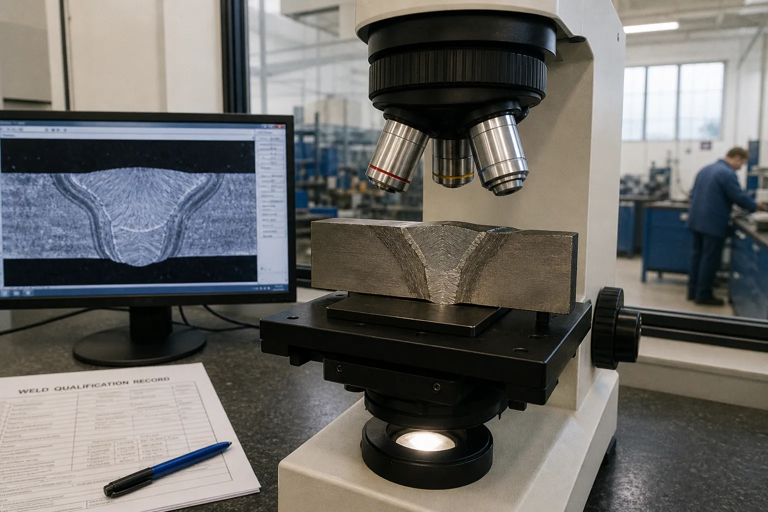
That is why welding procedure qualification testing does more than confirm that two pieces of steel can be joined. It establishes whether a defined combination of material, filler metal, heat input, preheat, travel speed, and technique can repeatedly produce a weld with the required strength, ductility, toughness, and soundness.
The central document in this process is the Procedure Qualification Record, or PQR. It captures what actually happened during the test weld — the measured voltage, amperage, travel speed, preheat temperature, joint details, consumables, and test results. The Welding Procedure Specification, or WPS, then uses the qualified results to define the operational ranges that welders may follow in production.
That distinction is simple, but it is where many weak qualification packages begin to soften at the edges.
The distinction between a PQR and a WPS
A WPS is an instruction for production welding. A PQR is evidence that the proposed instruction has produced an acceptable weld under test conditions.
The PQR records single-value actual parameters from the test coupon. If the welder used a particular amperage, voltage, travel speed, preheat temperature, electrode classification, and shielding arrangement, those values belong on the PQR as they were recorded during fabrication. The document is not a suggested range and not a convenient summary of what the welding team would prefer to use.
The WPS is different. It defines acceptable operating ranges derived from the qualified test results and governed by the applicable code. A WPS may therefore specify a range of amperage or travel speed, while the supporting PQR records the individual values used to qualify that procedure.
This relationship matters because the WPS cannot be treated as an independent recipe. Its ranges must remain supported by the qualification record, including the applicable essential variables. If a change moves beyond a variable or range that the governing standard treats as essential, the existing qualification may no longer support the revised procedure.
In practical terms, a PQR answers a historical question:
- What did the fabricator actually weld?
- Which materials and consumables were used?
- What thermal conditions were recorded?
- Which tests were performed on the completed coupon?
- Did the test results satisfy the relevant acceptance criteria?
The WPS answers the production question:
- What may the welder use on the shop floor?
- Within which ranges may the process operate?
- Which joint details, positions, materials, and consumables are covered?
- What limits must remain stable for the qualification to remain valid?
A complete welding procedure qualification testing requirements review therefore begins with the connection between these two documents, rather than reading either one in isolation.
A PQR is not a flexible instruction sheet — it is the measured evidence from which a controlled WPS earns its operating range.
Why actual recorded values matter
A test coupon can pass even when the documentation is poor, but the qualification package remains vulnerable if the recorded parameters are vague, rounded without justification, or copied from a planned WPS rather than captured during welding.
The purpose of recording actual values is traceability. When a test result later raises a question about fusion, toughness, hardness, or distortion, the engineering team needs to know what heat input and thermal history produced the coupon. An estimated parameter offers little support. A specific recorded value allows the result to be interpreted alongside the weld sequence and material condition.
The same principle applies to:
- Base-metal grade and thickness
- Filler-metal classification and diameter
- Welding process and polarity
- Preheat and interpass temperature
- Number and sequence of passes
- Joint preparation and backing
- Shielding gas or flux details
- Post-weld heat treatment, where required
- Welding position and progression
The governing standard determines which of these are essential variables and how changes affect the qualification range. ASME Section IX and AWS D1.1 do not create identical qualification systems, so a PQR prepared for one code should not automatically be treated as universally transferable to another. The materials, thickness ranges, test requirements, and acceptance criteria must be read within the standard being applied to the project.
Mechanical integrity: tensile and guided bend testing
The mechanical tests translate a welded joint from a visual object into a load-bearing specimen. They ask whether the weld can carry tension and whether the joint can deform without exposing a fundamental lack of fusion or unacceptable discontinuity.
Tensile testing
For a plate groove-weld PQR under AWS D1.1, tensile specimens are taken transversely across the weld and reduced to a section suitable for testing. The test measures ultimate tensile strength, or UTS, and the result must meet or exceed the minimum specified UTS of the base metal.
This is not a minor documentary formality. A welded joint may contain a bead profile that looks orderly and still fail to develop the required strength because of an unsuitable filler metal, inadequate fusion, excessive dilution, poor heat control, or an incompatibility between the base material and the deposited weld metal.
The tensile test helps answer one narrow but important question: can the qualified joint reach the required ultimate strength under tensile loading?
It does not answer every question. A passing tensile result does not establish low-temperature toughness, resistance to brittle fracture, or acceptable performance under cyclic service. Those properties require their own evaluation.
When reviewing the tensile portion of a PQR, the useful sequence is straightforward:
1. Confirm that the specimen orientation matches the applicable code requirement.
2. Check the identified base metal and its specified minimum strength.
3. Compare the reported UTS with the required minimum.
4. Review the fracture location and any recorded observations.
5. Confirm that the specimen dimensions and test method are documented sufficiently to support traceability.
The value of the test lies not only in the number produced by the machine, but in the relationship between the result, the material identification, the joint configuration, and the qualification limits later written into the WPS.
Guided bend testing
Guided bend testing looks at ductility and fusion soundness through a different movement. The specimen is bent through 180 degrees, forcing the welded region to stretch and reveal discontinuities that may remain hidden during a surface inspection.
Face, root, or side bends may be required depending on the governing standard and the thickness of the test coupon. Under the AWS D1.1 and ASME Section IX framework described in the qualification requirements, a plate thickness threshold of 3/8 inch separates conditions in which root and face bends may be used from those in which side bends are required. The exact specimen selection still depends on the applicable code edition and test configuration.
During a guided bend, the convex surface is examined for opened discontinuities. Under AWS D1.1, the convex surface of each bend specimen must not show a discontinuity exceeding 1/8 inch, or 3 mm, in any direction.
The test is especially useful because it does not ask the weld to remain visually unchanged. It asks the joint to tolerate severe deformation while maintaining continuity through the weld metal and fusion zones. A specimen may fail because of incomplete fusion, slag entrapment, cracks, lack of penetration, or another defect that was not obvious before bending.
The difference between the bend types is also meaningful:
- A face bend places the weld face on the outside of the curve and examines the deposited surface and upper fusion region.
- A root bend places the root on the outside and challenges the root profile and root fusion.
- A side bend exposes a longitudinal side surface, making it useful when the coupon is thick enough that a full face or root bend would not provide the intended examination.
Tensile and bend tests therefore work as complementary evidence. Tensile testing measures the strength of the assembled joint under axial load. Bend testing exposes how the weld and adjacent material behave when stretched through a tight, controlled deformation.
Strength tells you how much the joint can carry; a guided bend shows whether the joint can yield without opening the weaknesses it was hiding.
Verifying toughness: the Charpy V-Notch test
Strength and ductility are not the same as toughness. A weld can satisfy a tensile requirement and survive a bend test while still presenting a serious risk in low-temperature service if its notch toughness is inadequate.
The Charpy V-Notch, or CVN, impact test evaluates the energy absorbed by a notched specimen during fracture. It is used to assess resistance to brittle fracture, particularly when the component may experience low temperatures, dynamic loading, restraint, or a combination of these conditions.
The test temperature is critical. For procedure qualification connected to low-temperature service, Charpy testing must be performed at the Minimum Design Metal Temperature, or MDMT, rather than simply at room temperature. Toughness is strongly temperature-dependent, and a result produced in a warm laboratory environment cannot automatically represent the behavior of the weld at the lowest design condition.
A Charpy result should therefore be read alongside:
- The specified MDMT
- The material grade and product form
- The weld-metal and heat-affected-zone sampling location
- The notch orientation
- The required absorbed energy
- The governing code and project specification
- Any supplementary toughness requirements
A typical Charpy V-Notch testing machine may have a standard capacity of 300 joules under commonly used ISO 148-1 or ASTM E23 equipment arrangements, but machine capacity is not itself a qualification result. The meaningful information is the energy absorbed by the correctly prepared specimen at the required temperature and the acceptance criterion assigned by the governing standard.
The location of the notch matters because the weld is not a single uniform material. Weld metal, fusion boundary, and heat-affected zone may respond differently. A procedure with excessive heat input can alter the grain structure in the HAZ; a different filler metal can change weld-metal toughness; an unsuitable interpass condition can shift the thermal history again. These are reasons the qualification record must preserve the process details rather than reduce the procedure to a brand name or a general welding method.
Why a tensile pass is not enough
One of the most persistent errors in procedure qualification is treating tensile strength as a broad guarantee of weld performance. It is not.
A passing tensile test demonstrates compliance with the tensile requirement for that test condition. It does not prove that the joint will meet the required Charpy impact energy at the MDMT. It does not establish fatigue performance. It does not confirm that a coating will adhere after fabrication, that residual stress has been adequately controlled, or that production welds will match the coupon if the essential variables drift.
The qualification package has to be assembled as a set of answers, each addressing a different failure mode:
| Qualification evidence | What it primarily examines | What it does not establish by itself |
|---|---|---|
| Tensile test | Ultimate strength of the transverse welded joint | Low-temperature toughness or fatigue resistance |
| Guided bend test | Ductility, fusion soundness, and opened discontinuities | Full service-life performance |
| Charpy V-Notch test | Notch toughness and resistance to brittle fracture | General weld quality outside the tested condition |
| Macro-etch examination | Penetration, fusion, weld geometry, and large-scale flaws | Detailed microstructural phase behavior |
| Micro-examination | Grain structure and selected HAZ or weld-metal changes | Broad production conformity without process control |
This separation keeps the review grounded. Each test has a role, and none should be asked to carry the meaning of all the others.
Structural and microstructural analysis
Mechanical tests show how a coupon behaves under a defined load. Metallographic examination shows what the weld looks like inside its section — where the fusion line travels, how deeply the weld penetrates, whether the passes have merged, and how the heat has shaped the surrounding material.
Macro-etch examination
A macro-etch specimen is prepared so that the overall weld cross-section becomes visible. The examination can reveal:
- Penetration depth
- Fusion between weld passes
- Fusion with the base metal
- Root profile
- Bead arrangement
- Large-scale inclusions or voids
- Undercut, overlap, or other geometric conditions
- Discontinuities that are not evident from the surface
Macro-etching is particularly valuable because it connects the visible welding technique with the internal result. A stable-looking bead does not guarantee adequate root penetration. A procedure may produce a neat cap while leaving an internal lack of fusion between passes. The cross-section settles those questions more directly.
For a steel fabrication shop using automated or semi-automated processes, macro examination can also help identify whether the selected travel speed, current range, joint preparation, and pass sequence are producing the intended geometry. It is not a replacement for production inspection, but it is a powerful way to understand the process before it is released into repetitive work.
Micro-examination and the heat-affected zone
Micro-examination works at a finer scale. It examines grain structure, phase changes, and the character of the heat-affected zone that develops beside the fusion boundary.
It is not automatically required for every ordinary structural qualification. Its use becomes more selective where the application involves high-alloy materials, sour service, low-temperature requirements, or other conditions in which metallurgical behavior carries a greater risk.
The HAZ deserves particular attention because it is neither the original base metal nor deposited weld metal. It has experienced a thermal cycle, and the temperature reached, the time at temperature, the cooling rate, and any post-weld heat treatment can alter its microstructure. A procedure that appears mechanically adequate in one material system may not provide the same margin in another.
This is also where welding procedure qualification connects with heat-treatment planning. Preheat can slow cooling and help manage hydrogen-related risks. Interpass control shapes the thermal cycle from one pass to the next. Post-weld heat treatment may be used to reduce residual stress or achieve a specified metallurgical condition, depending on the material and governing requirements. These controls must be treated as part of the qualified procedure rather than as shop preferences added later.
The examination does not need to become a lecture in metallurgy to be useful. Its practical question is clear: did the qualified thermal cycle create a structure compatible with the service demands placed on the joint?
Non-destructive examination of the qualification coupon
Mechanical and metallographic testing are supported by non-destructive examination, which looks for discontinuities without destroying the entire test article.
The exact combination depends on the applicable code, project specification, material, joint type, and service conditions. Common methods include visual examination, radiographic testing, and ultrasonic testing, with other methods selected when the expected defect type or geometry requires them.
Visual examination is the first layer. It can identify surface cracks, undercut, overlap, arc strikes, poor contour, excessive reinforcement, and other visible conditions. It cannot reveal every internal discontinuity, but it can quickly show whether the coupon was made under controlled conditions.
Radiographic testing can reveal volumetric discontinuities such as certain types of porosity, slag inclusions, and incomplete penetration, depending on the geometry, material thickness, technique, and sensitivity achieved. Ultrasonic testing can be useful for planar reflectors and internal conditions in thicker sections, but its reliability depends heavily on calibration, probe selection, surface condition, operator competence, and interpretation.
Non-destructive examination should not be treated as a decorative certificate attached after mechanical testing. It helps establish that the coupon subjected to tensile, bend, or impact testing represents a weld with acceptable internal condition. When the test specimen is cut from a defective or unrepresentative area, the mechanical result may be difficult to interpret.
For that reason, the welding procedure specification coupon inspection should remain connected to the sequence of fabrication:
1. Confirm material and joint preparation before welding.
2. Record actual welding parameters during coupon fabrication.
3. Perform the required visual and non-destructive examinations.
4. Locate and extract mechanical specimens according to the governing standard.
5. Complete tensile, bend, impact, or metallographic tests as required.
6. Compare each result with the relevant acceptance criterion.
7. Use the completed PQR to establish the supported WPS ranges.
The order is not merely administrative. It creates a chain of evidence from the material certificate and joint preparation to the final test result.
Navigating AWS D1.1 and ASME Section IX
The phrase “welding procedure qualification” can sound universal, but qualification is always attached to a code, specification, or contractual framework. AWS D1.1 is widely associated with structural steel welding, while ASME Section IX provides qualification rules used in pressure equipment and related applications. Other standards, including ISO-based systems, may define their own essential variables, test arrangements, ranges, and acceptance criteria.
The same weld procedure may therefore require a careful code-by-code review rather than a simple document transfer.
Essential variables in welding procedure qualification
Essential variables are the changes that can affect the qualified performance of the procedure enough to require requalification or a revised qualification range. Their treatment varies with the governing standard, but the review commonly focuses on changes involving:
- Base-metal grouping, grade, or thickness
- Filler-metal classification, diameter, or deposited chemistry
- Welding process
- Joint design, backing, or groove preparation
- Preheat and interpass temperature
- Heat input or travel speed
- Welding position and progression
- Shielding gas, flux, or polarity
- Number of passes and thermal controls
- Post-weld heat treatment
- Impact-test requirements or service temperature
The precise limits must come from the applicable code and project requirements. A general statement that a procedure is “qualified” is incomplete unless it identifies what is qualified, under which standard, and within which ranges.
Prequalified WPS is a separate pathway
AWS D1.1 may permit certain prequalified WPS arrangements when the specified joint designs, base materials, filler combinations, and other conditions conform to the code’s defined requirements. A prequalified WPS is not the same thing as a WPS supported by physical coupon testing.
That distinction matters in both directions. A fabricator should not assume that every AWS D1.1 WPS requires a PQR coupon, because eligible prequalified arrangements may be exempt from physical qualification. At the same time, a procedure that falls outside the prequalified conditions cannot borrow that exemption simply because the welding process is familiar.
Where physical qualification is required, the PQR must stand on its own evidence. It cannot be replaced by a generic WPS, a welder qualification, or a production weld visual inspection.
Thickness ranges and specimen selection
The test coupon thickness affects both specimen selection and the range that the qualification may support. The 3/8-inch threshold associated with root/face versus side bends is one example of how a seemingly small dimensional distinction can alter the testing route.
This is why a qualification review should not begin with the question of whether the laboratory report says “passed.” It should begin with whether the right coupon was welded, the right specimens were extracted, and the correct test arrangement was applied to the intended production range.
A technically impressive report attached to the wrong configuration remains the wrong qualification.
What a defensible PQR package looks like
A strong PQR package is not necessarily the longest one. It is the one that allows another competent reviewer to follow the path from proposed procedure to tested result without filling gaps with assumptions.
At minimum, the record should make the following relationship visible:
- The material welded in the coupon is identified.
- The joint configuration is described clearly.
- The actual welding parameters are recorded as single values.
- The thermal controls are documented.
- The examination and test methods are identified.
- The results are reported against the applicable acceptance criteria.
- The qualification range is transferred correctly into the WPS.
- Any limitations, supplementary requirements, or code-specific conditions remain visible.
This is also where quality systems such as ISO 9001 can support the technical work, although certification alone does not make a welding procedure qualified. A quality management system can provide control over document revision, material traceability, calibration, nonconformance handling, laboratory records, and approval workflows. The technical qualification still depends on the correct code, competent testing, and compliant results.
The same principle applies to production control. A qualified procedure can lose its meaning if shop-floor practice drifts beyond the essential variables, if consumables are not controlled, if preheat is assumed rather than measured, or if welders work from an obsolete WPS revision.
Qualification is therefore not a single event that ends when the laboratory report arrives. It is the point at which a controlled welding process becomes supportable — provided the production process continues to resemble the process that was tested.
Final view
PQR testing verifies more than whether a weld looks acceptable after fabrication. It establishes a technical boundary around a welding process: these materials, these joint conditions, these thermal controls, these recorded parameters, and these test results support this range of production work under this governing standard.
Tensile testing addresses strength. Guided bends examine ductility and fusion soundness. Charpy testing addresses notch toughness at the temperature where brittle fracture is a real design concern. Macro-etching reveals penetration and internal geometry. Micro-examination, where required, opens the finer story of grain structure and heat-affected-zone behavior. Non-destructive examination connects these tests to the internal integrity of the coupon.
The most reliable qualification packages do not force one test to prove everything. They allow each test to answer its own question, then bring those answers together in a traceable PQR and a carefully bounded WPS.
That is the steady work of welding procedure qualification — not a signature at the bottom of a form, but a measured way to help the joint carry its future load.