Space Trusses vs Plate Girders for Pipe Bridges
Most pipe bridge design decisions get made long before the structural model sees its first load case — and most of them default to a plate girder layout. That default is correct up to roughly 15 meters of span.
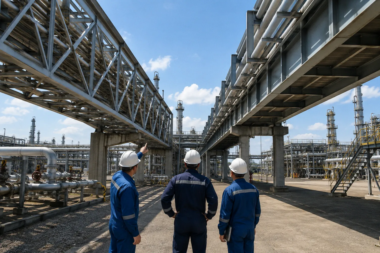
Above that line, the same default quietly burns through ten metric tons of steel on a 30-meter petrochemical bridge, with a cost delta landing near thirteen and a half thousand US dollars on the primary structure alone. The space truss vs plate girder pipe bridge call is not exotic. It is a span-versus-system judgment that procurement teams, EPC contractors, and detailers keep repeating because plate girders feel safer, simpler, and more familiar. They are — up to a point.
Structural Mechanics: Bending vs Axial Force Distribution
The decision between a plate girder and a space truss is, underneath the procurement documents, a decision about how the steel wants to carry load.
A plate girder resists gravity, pipe contents, wind, and thermal movement through flexural action. Vertical loads enter the horizontal flanges as compression on top and tension on the bottom. Shear travels down a continuous, solid web plate that connects those flanges into a single I-shaped section. The behavior is intuitive: stiffer section, deeper web, thicker flanges, more capacity. The structural action is local and bending-dominated, which means the steel near the neutral axis does comparatively little work, and the material near the outer fibers does almost all of it.
A space truss works through a three-dimensional triangulated network of chords, web members, and bracing tubes. Loads resolve into tension and compression along each member rather than bending. The efficiency of triangulated geometry is that every member can be sized to its actual force demand, and material ends up concentrated where the structural math actually needs it. The trade-off is geometric complexity: nodes, gusset plates, often tubular sections with welded end connections, and a detailing tolerance chain that demands discipline.
Plate girders fight load with bending. Space trusses fight load with geometry. That difference is the entire selection problem in one sentence.
The 15-Meter Threshold: Economic Span Ranges for Industrial Bridges
The span number on the drawing is the first filter, and it is the one most projects misjudge.
Comparative structural work on industrial pipe bridges consistently puts plate girders in their economical sweet spot at spans up to roughly 15 meters. Inside that range, the fabrication simplicity wins: cut two flanges to length, weld a web between them, stiffen the bearing zones, ship it. There is no node-welding cluster to coordinate, no tubular chord intersection to clash-detect against the piping model, and the erection crew can set girders with a pair of cranes and a standard rigging plan.
Beyond 15 meters, the math changes. Plate girder depth has to grow roughly in proportion to span to keep deflections and stresses within petrochemical serviceability limits. Once the web plate starts approaching the limits of practical shipping — typically when the section gets deep enough that transport becomes a permitting exercise — the girder either needs field splices, a haunched profile, or both. None of those are free.
A space truss does not need to grow linearly with span. Triangulated geometry lets chord forces scale with span while member counts and node counts grow more slowly. Above 15 meters — and especially in the 20 to 30-plus meter band that covers most refinery and large chemical plant pipe bridges — trusses start returning material savings that compound quickly.
Below roughly 15 meters, plate girders almost always win on cost and simplicity — but project-specific loads, utility routing, and fabrication capability can shift that line. Above it, the economics begin arguing in the truss's favor with every additional meter.
Material Efficiency and Cost Analysis for Long-Span Pipe Racks
The cleanest demonstration of the crossover is the 30-meter span case. In a comparative study published through SciELO-indexed structural engineering literature, swapping a plate girder layout for a space truss layout over a 30-meter petrochemical pipe bridge reduced steel consumption by more than 10 metric tons on the primary structure. The reported cost delta landed at 13,587.62 USD on structural steel alone, before fabrication labor, transport, and field erection were even factored in.
That is a single decision on a single span. Pipe bridges in a refinery or large chemical complex are rarely singletons. A typical piperack corridor involves multiple parallel bridges carrying process lines, utilities, and sometimes cable trays across roads, tank farms, and equipment rows. Multiply the 30-meter case by five or ten parallel bridges and the steel tonnage differential scales directly into procurement, fabrication, and painting costs.
The table below captures the practical decision variables side by side:
| Parameter | Plate Girder | Space Truss |
|---|---|---|
| Primary load mechanism | Bending and shear in solid web and flange plates | Axial tension and compression in triangulated members |
| Economical span range | Up to roughly 15 m | Above 15 m, with growing advantage toward 30+ m |
| Steel weight at 30 m span | Baseline reference | More than 10 MT lighter |
| Reported cost delta at 30 m | Baseline reference | About 13,587.62 USD lower on steel |
| Resistance to concentrated point loads | Excellent — flange receives load directly | Adequate, provided loads land near panel nodes |
| Fabrication tolerance sensitivity | Moderate, solid sections forgive small drift | High — node geometry controls member fit |
| Routing utilities through structural depth | Poor — solid web blocks internal routing | Excellent — open bays invite cable trays and small-bore lines |
| Typical fabrication skill required | Standard heavy-plate practice | Higher — node welding and tubular detailing competence |
The last row on that table is not a side note. On a process plant piperack, the structural depth is rarely the only thing occupying it.
Fabrication Realities: Plate Girder Tolerances and Truss Node Complexity
Plate girders reward fabrication shops that already own flame-cutting tables, press brakes, and submerged-arc welding bays. For heavy industrial work, fabricators commonly work to ASTM A709 or AASHTO M 270 specifications — Grade 50 is the routine baseline — with web and flange plate cutting tolerances as tight as ±0.5 mm on laser-cut edges. Flange plate thicknesses for fabricated plate girder sections typically range from 14 mm up to 80 mm, which covers most petrochemical pipe bridge demands without forcing the section into a rolled product.
The advantages are real. Plate girders handle concentrated point loads — heavy valve assemblies, large-diameter pipe shoes, equipment supports landed mid-span — without much complaint. The flange directly receives the load, and local stiffeners can be detailed to spread the bearing pressure. Fabrication shops that have invested in I-line welders and ultrasonic testing setups can produce plate girders at a known cost on a known schedule.
Space trusses ask more of the shop. Triangulated geometry means that every node is a fabrication event: cut tubes to length with mitred ends, weld gusset plates or use welded socket connections, verify member lengths against the 3D model, ship in trial assemblies where geometry matters. The structural steel is lighter — that 10-ton-plus saving did not materialize from nowhere — but the labor hours shift from welding long seams to setting out and welding concentrated node clusters. A shop that runs plate girder production at a known rhythm can find itself rebuilding its planning assumptions when a truss order lands.
This is the part the procurement spreadsheet does not see. A truss that is 10 MT lighter on paper can still cost more if the shop charges for node complexity, trial assembly time, and inspection hours that a plate girder simply does not require. That trade-off tends to break even somewhere in the 18 to 22 meter range in practice, which is why the 15-meter threshold should be treated as a soft line, not a wall.
Utility Integration: Open-Web Trusses vs Solid-Web Girder Constraints
Petrochemical pipe bridges are rarely just pipe bridges. They are utility corridors. Process lines, instrument air, electrical cable trays, small-bore chemical lines, firewater, and foam agent piping all want to travel the same right-of-way. The question is not whether they can be added on top of the bridge — they almost always can — the question is whether they can pass through the structural depth cleanly. On a multi-level piperack, that distinction matters.
A plate girder fills its depth with steel. The solid web blocks any attempt to route utilities through the section. Cable trays must hang below the bottom flange or sit beside the girder on outriggers. Small-bore lines either get their own support steel or are clamped to the main pipe shoes. None of that is fatal — it is how most short-span pipe bridges in the industry are detailed — but it adds support steel, adds clamps, adds another set of drawings to coordinate, and another set of clash points to resolve against the piping model.
An open-web space truss invites utilities through the structural depth. The triangulated geometry creates clear bays where cable trays, conduit, and small-bore utility lines can run between the chords without additional support structure. For tight right-of-way situations — plant perimeters, congested tank farm crossings, intra-unit pipe bridges where every meter of width is contested — that geometric freedom is often the deciding factor, even before the steel weight comparison is finished.
There is a limit. Heavy process piping should never be routed through truss bays in a way that loads the bracing members with concentrated forces the geometry was not designed to carry. The rule is the same as for any truss — keep heavy pipe shoes near panel points, and use the open bays for what they are good at: lighter utilities, conduits, and instrument runs.
When the Plate Girder Still Wins
The case for plate girders is not historical nostalgia. There are real conditions where the plate girder remains the correct answer, and pretending otherwise is the kind of engineering groupthink that produces expensive rework.
Short spans under 15 meters are generally plate girder territory. The fabrication cost per ton is lower, the shops know it, the erection crews know it, and the steel weight penalty is small in absolute terms. For pipe bridges spanning roadways, short equipment gaps, or internal piperack segments where columns can be set economically, the plate girder remains the pragmatic choice — though projects with unusual loading, tight utility bays, or a fabricator already set up for tubular work can justify running a comparison even below that line.
Concentrated load conditions also favor plate girders. Large-diameter pipe crossings, equipment support landings, and asymmetric pipe loads from heavy reactors or compressors all push the design toward a section that can receive a localized load without node-by-node detailing. A space truss can do this work, but it requires careful panel layout to land the load near a node, and the design becomes noticeably less forgiving.
Plate girders also remain the lower-risk choice for fabricators without established tubular truss capability. A shop that runs certified plate girder welders but only occasional truss work will produce a plate girder faster, cheaper, and with fewer inspection surprises than a space truss of equivalent span.
The selection problem is not a software problem, and it is not a code problem. It is a span judgment made before the structural model gets its first load case. Get that judgment wrong and the structure either carries ten extra metric tons of steel through fabrication, transport, and painting, or it carries the schedule and inspection cost of a node-heavy truss the shop was not optimized to produce.
The practical filter is short. Below about 15 meters, plate girders are generally the more economical and straightforward choice — but the decision still deserves a project-specific look when utility routing, concentrated loads, or fabrication conditions push the design outside the typical case. Between 15 and 22 meters: run both, compare on steel weight and shop labor, expect the result to be close. Above 22 meters — and certainly at 30 meters and beyond — a space truss is almost always the cheaper steel solution by a margin procurement will not wave away. The 13,587.62 USD delta on a single 30-meter span is the kind of number that survives any contingency adjustment.
Then layer the utility integration question on top — will cable trays, small-bore lines, and instrument runs need to pass through the structural depth? — and the truss argument gets stronger. Layer the concentrated-load profile on top — heavy valves landed off-node, equipment supports landing mid-panel — and the plate girder argument comes back.
Run both. Look at the tonnage, the shop hours, and the utility routing on the same drawing. Then decide. The pipe bridge is too visible an item on the structural steel list to let it default to whichever system the detailers happened to have open in the CAD template.