Anchor Bolt Tolerances for Petrochemical Column Foundations
When a 1,200-ton hydrocracker reactor is ready to lift—and the window between crane positioning and final set narrows to hours, sometimes minutes—the entire sequence still rests on a quieter decision…
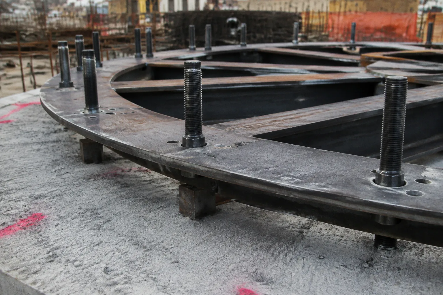
When a 1,200-ton hydrocracker reactor is ready to lift—and the window between crane positioning and final set narrows to hours, sometimes minutes—the entire sequence still rests on a quieter decision made weeks earlier in the foundation pit: how accurately the anchor bolts were set into the concrete.
Get it right, and the vessel settles onto its base ring with a clean, centered fit. Get it wrong, and the erection crew is looking at a vessel with nowhere to go while a multi-thousand-ton module is still hanging in the slings. That pause, between template survey and concrete pour, is where petrochemical construction either earns its schedule or starts spending it.
This is where petrochemical vessel anchor bolt tolerance checks become more than a paperwork exercise. The work is not limited to checking whether a bolt is roughly in the right place. Projection, bolt-group location, spacing, inclination, sleeve condition, template rigidity, and the clearance shown on the equipment drawing all have to work together. A foundation can appear acceptable by a general concrete tolerance and still reject the vessel baseplate.
Navigating the Conflict Between Concrete and Steel Standards
The first point to settle—before the template is fabricated and before the rebar cage is closed—is which requirement governs the anchor bolts. There is rarely one universal tolerance that can be applied without reading the project documents.
Three specifications commonly appear on petrochemical sites, but they address different parts of the work. ACI 117 is concerned with construction tolerances for concrete and embedded items. AISC 303 addresses the conditions needed for steel erection. PIP standards are written for process-industry projects, where the foundation and the equipment-supporting steelwork have to meet in a much narrower practical window.
That difference matters. A general embedded-item tolerance in a concrete standard should not automatically be treated as the acceptance criterion for a vessel anchor-bolt group. Concrete construction can be within its broad placement tolerance while the bolt pattern is still unusable for a machined base ring or a fabricated column support.
AISC 303 approaches the issue from the steel side. The erector needs the anchor bolts to match the holes in the baseplate without field enlargement, forced installation, or improvised cutting. PIP requirements then provide project-specific controls for petrochemical foundations, including projection, group location, and spacing where those requirements are incorporated into the contract documents.
The governing hierarchy should therefore be established in writing:
1. Start with the project specification and equipment foundation drawing.
2. Identify the standard explicitly referenced for anchor-bolt installation and acceptance.
3. Check whether the vessel manufacturer has issued tighter requirements than the general civil specification.
4. Confirm the baseplate or base-ring hole pattern against the latest approved fabrication drawing.
5. Use general concrete tolerances only for the items they actually cover.
If the project specification references PIP STS03001, that document governs the relevant foundation tolerances unless the contract or approved equipment documents impose a tighter requirement. It is not enough to cite the standard from memory. The applicable edition, table, drawing note, and any project deviation should be available to the survey and quality teams before the template is released for fabrication.
| Parameter | Concrete-side concern | Steel or equipment-side concern | Field implication |
|---|---|---|---|
| Embedded-item location | General placement of items cast into concrete | Exact bolt-group relationship to the column or vessel centerline | A broad concrete tolerance may not be suitable for a base ring |
| Bolt projection | Final concrete elevation and template setting | Nut engagement, washer fit, and baseplate seating | Projection must be checked at the actual bolt locations |
| Bolt-to-bolt spacing | Stability of the template during the pour | Match with the fabricated hole pattern | A group can be correctly located but still unusable if its internal spacing is wrong |
| Bolt inclination | Movement during reinforcement and concreting | Nut installation and clearance through the hole | Inclination is checked on the individual bolt, not only at group center |
| Sleeve condition | Protection during the pour | Available lateral adjustment | A blocked or concrete-filled sleeve provides no useful adjustment |
The practical conflict is straightforward: the concrete crew is building a foundation, while the mechanical and steel crews are trying to install a manufactured object with a fixed geometry. The foundation standard and the equipment drawing must be reconciled before the concrete is placed, not after the vessel arrives.
The column lands on the foundation—never the other way around. Anchor bolts are the alignment pins the entire erection sequence trusts.
Critical Dimensional Tolerances for Bolt Groups and Projections
Once the governing documents are identified, three dimensions become the working envelope: projection above concrete, bolt-group location, and bolt-to-bolt spacing.
Projection above concrete
Projection is frequently overlooked because it becomes visible as a problem only when the steel or vessel is already at the foundation.
Under the project-specific PIP requirement cited for this type of work, anchor bolt projection above the top of concrete is controlled within a range from zero to the specified positive limit. In the referenced requirement, that limit is 6 mm. The important feature is the one-sided nature of the tolerance: the bolt must not finish below the required top-of-concrete reference.
A bolt that is too low can leave insufficient thread for the nut and washer assembly. A bolt that is too high can interfere with the baseplate, reduce the available grout space, or prevent the base ring from seating as intended. Neither condition should be corrected by forcing the vessel down or by modifying the connection at the foundation.
Projection is controlled by template elevation and the relationship between the template, the finished concrete surface, and the embedded length of the bolt. Bolt length alone does not establish the final projection. That is why the template elevation must be surveyed and why the concrete top level has to be controlled as carefully as the bolt itself.
On heavy column foundations, a few millimetres can consume a significant part of the available tolerance. The check should therefore include:
- the target elevation of the template;
- the elevation of the top of each bolt or bolt group;
- the anticipated finished concrete elevation;
- thread condition and usable thread length;
- the washer and nut arrangement shown on the approved connection detail.
Bolt-group location
The bolt group must be checked against the column line, vessel centerline, or other reference established by the foundation drawing. Under the cited PIP requirement, the group location is controlled to ±6 mm relative to the specified line.
This is not the same as checking one convenient point at the center of the template. A template may have the correct center while one side of the bolt pattern has distorted, or the center may be correct while the entire pattern is rotated. The survey should record the coordinates of the group and, where the geometry requires it, the orientation of the pattern.
A base error also affects later plumb checks. A tall column can sometimes be brought into vertical alignment, but correcting a foundation error with shims or forced positioning changes the load path and consumes the adjustment intended for final erection. The higher the vessel, the less sensible it is to treat a base-location error as a cosmetic issue.
Bolt-to-bolt spacing
Internal spacing within the group is normally the tightest dimensional control. The cited PIP and steel-erection requirements use a limit of approximately ±3 mm for the relevant spacing control.
The spacing check must follow the actual baseplate geometry. Measuring only adjacent bolts is not enough when the pattern includes diagonals, multiple bolt rows, or a circular base ring. The survey and inspection team should compare the measured pattern with the approved equipment drawing, including:
- center-to-center spacing between adjacent bolts;
- diagonals across the group;
- bolt-circle diameter where applicable;
- orientation of the pattern to the vessel axes;
- relationship between the bolt group and the foundation centerline.
A bolt group can be within its location tolerance and still fail because its internal dimensions have opened up or contracted. Conversely, a group with correct internal spacing may be positioned too far from the column line. These are separate checks and should not be combined into a single statement that the template is “in position.”
Baseplate and base-ring holes
The hole pattern is part of the interface and must be reviewed from the approved fabrication documents. General clearance values should not be copied from a remembered table or presented as a universal AISC or PIP allowance. Hole diameter depends on the bolt size, hole category, connection design, base-ring detail, governing standard, and project specification.
The correct field question is not whether a generic hole clearance seems generous. It is whether the measured bolt pattern fits the holes shown on the current approved drawing while preserving the required edge distances, washers, nut engagement, and load-transfer arrangement.
Before fabrication and again before erection, the team should verify:
- bolt diameter and grade;
- hole diameter and hole type;
- hole orientation and slot direction, if slots are permitted;
- washer dimensions;
- base-ring or baseplate thickness;
- edge distance around each hole;
- whether the upper and lower rings have different detailing;
- whether any adjustment is permitted by the equipment manufacturer.
Some vertical vessels use different clearances at different support rings because the rings perform different functions. The base ring transfers the operating load and may have a different hole arrangement from a top guide or stabilizing ring. That distinction must come from the approved drawing and design documentation. It should never be recreated in the field by enlarging holes or assuming that both rings can use the same template geometry.
Hole clearance is not a substitute for a survey. It is a designed part of the connection, with limits that belong to the approved equipment detail.
Managing Vertical Inclination and Lateral Sleeve Adjustments
Position and projection are not the only concerns. Every anchor bolt must also remain sufficiently vertical, and every sleeve must retain the adjustment capacity for which it was designed.
Vertical inclination
The cited petrochemical installation guidance limits bolt inclination by a 1:40 slope ratio. In practical terms, the permitted lateral departure increases with bolt length, but the relationship must be checked against the actual free length and the project requirement. A 600 mm free length, for example, corresponds to a maximum theoretical departure of 15 mm under that ratio.
That calculation does not mean the bolt can be allowed to lean freely. A leaning bolt may still pass through the baseplate hole but bind against the washer or nut. It can also reduce the effective bearing area or make it impossible to install the nut without damaging the threads. The acceptance check should consider both the stated slope ratio and the physical fit of the complete connection.
Inclination is usually introduced while the template is being fixed, while reinforcement is adjusted, or while concrete is being placed. A template can be correctly surveyed before the pour and still move when the concrete is discharged against it. Long bolts are particularly sensitive to small angular movements because the free end magnifies the displacement.
Rigid templates, cross-bracing, and positive attachment to stable parts of the reinforcement cage are therefore more reliable than a light frame held in place by a few temporary ties. The fixing method must not damage the bolts or introduce a prohibited weld.
Sleeve adjustment
Anchor sleeves provide limited lateral movement between the bolt and the surrounding concrete. They are useful when the design intentionally allows a small adjustment during equipment setting, but they are not a repair method for a misplaced template.
The cited API 686 guidance limits the usable lateral movement inside the sleeve to approximately 6.5 mm. The project documents should be checked before applying that value, particularly where the sleeve detail is part of a vessel foundation rather than rotating-equipment installation.
The sleeve has to remain open, clean, and properly sealed during the pour. A concrete-filled sleeve is no longer an adjustable sleeve. Foam plugs, caps, or other approved seals should be installed before concrete placement, and the condition of each sleeve should be checked after stripping. A missing seal can turn a designed adjustment into a rigid obstruction.
The following controls are worth treating as separate inspection points:
- verify the bolt inclination against the project limit;
- confirm that the bolt remains clear inside the sleeve;
- inspect sleeve caps or seals before the pour;
- check that concrete has not entered the sleeve after stripping;
- confirm that the available movement is consistent with the approved detail;
- never enlarge a baseplate hole or cut a bolt to compensate for a survey error without engineering approval.
Best Practices for Pre-Pour Template Inspection and Positioning
The decisive inspection occurs before the concrete truck arrives. After the pour, a correctable layout issue becomes an embedded steel problem.
The template should be fabricated as a rigid frame matched to the approved bolt pattern. For heavy column foundations, a steel template or steel ring with adequate bracing is generally more dependable than a flexible sheet or lightly supported frame. The template has to carry the dead weight of the bolts, nuts, sleeves, and temporary supports without sagging or rotating.
The frame should be positioned by survey against established project control points. Tape measurements remain useful for local verification, but they do not replace a total-station survey when the foundation carries a large vessel or column. The inspection should record the coordinates rather than relying on a visual statement that the template is centered.
A practical sequence is:
1. Confirm the latest approved foundation, equipment, and anchor-bolt drawings.
2. Check the bolt diameter, spacing, orientation, projection target, and sleeve detail against those drawings.
3. Inspect the template for rigidity, dimensional accuracy, and damage before it is brought to the foundation.
4. Set the template to the project control lines using survey equipment.
5. Check the elevation of the template and calculate the expected bolt projection above finished concrete.
6. Verify bolt-to-bolt spacing, bolt-circle dimensions, diagonals, and pattern orientation.
7. Check the vertical inclination of the bolts before reinforcement is closed around the assembly.
8. Fix the template to a stable support system without tack-welding the anchor bolts.
9. Protect the sleeves and confirm that no obstruction can enter during the pour.
10. Repeat the survey after rebar placement and immediately before concrete placement.
11. Record the measured coordinates and elevations on the inspection documentation.
12. Obtain the required civil, survey, mechanical, and quality approvals before the pour release.
The prohibition on tack-welding anchor bolts is not a minor preference. Heat can affect the bolt material, while a weld bead or spatter can interfere with thread engagement. The bolt should be restrained by the approved template, clamps, nuts, bracing, or other accepted methods.
The rebar cage also deserves a specific check. Rebar chairs can settle, reinforcing bars can be repositioned to clear a sleeve, and workers can lean against the template while tying the cage. Any of those actions can move the bolt group. The final survey must therefore take place after the reinforcement arrangement is complete, not merely after the template was first installed.
Photographs are useful when they support the survey record. Views from above and from the sides can show the template supports, sleeve seals, bolt condition, and relationship to the reinforcement. They do not replace measured coordinates, but they make it easier to understand what was actually installed if a question arises later.
The as-built record should identify the foundation, bolt group, survey date, control points, measured coordinates, elevations, inclination results, and disposition of any deviation. A small discrepancy found before the pour can normally be discussed and corrected with the relevant disciplines present. The same discrepancy discovered during a vessel lift may require a formal engineering assessment, revised lifting planning, or removal of already placed concrete.
The pre-pour survey is the last inexpensive point at which the foundation can be corrected. After the concrete sets, every millimetre becomes harder to own.
Resolving Field Misalignments Beyond Baseplate Clearance Limits
Even with a disciplined routine, field deviations occur. A template may move during the pour, a rebar support may settle, or a survey reference may be transferred incorrectly. The key is to classify the deviation before anyone attempts a physical correction.
First determine what has moved:
- the complete bolt group relative to the foundation centerline;
- one or more bolts within the group;
- the bolt projection;
- the bolt inclination;
- the sleeve itself;
- the finished concrete surface;
- or the fabricated baseplate or base ring.
Then compare the measured condition with the applicable limits and the actual equipment geometry. A group-location error is not equivalent to a spacing error. A low bolt is not repaired by moving the entire template. A blocked sleeve is not corrected by adding a thicker washer.
The base ring may provide designed clearance, but that clearance should be treated as part of the approved connection—not as an invitation to accept uncontrolled drift. The available movement must be checked against the measured hole diameter, bolt diameter, washer size, edge distance, and the manufacturer’s installation requirements. The field team should not infer permissible movement from a visual gap.
Possible responses depend on the deviation and must be approved by the responsible engineer. They may include controlled repositioning before grouting, an engineered washer or sleeve detail, correction of the concrete surface, replacement of a damaged component, or a revised connection detail. In some cases, the correct solution is to stop the erection sequence while the design team evaluates the condition.
Shims and grout
Shims are often used to establish elevation and support the base ring before grouting, but they should not become a hidden correction for an out-of-position anchor group. Excessive or uneven shim stacking can reduce bearing contact, create local stress concentrations, and leave the grout bed with an unintended thickness.
Before using shims, verify:
- the required base elevation;
- the permitted grout thickness;
- the bearing area available under the base ring;
- the location of the shims relative to load-transfer points;
- whether the vessel manufacturer permits the proposed arrangement;
- whether the shim material and configuration are approved.
If the baseplate cannot sit within the intended geometry without a large improvised shim stack, the issue has moved beyond normal erection adjustment. The condition should be documented and referred for engineering disposition.
Field hole enlargement
Field enlargement of a baseplate or base-ring hole is one of the most tempting and least defensible shortcuts. It changes the connection detail, may reduce edge distance, can affect washer seating, and can compromise the design assumption behind the bolt group. It also makes the original survey error harder to trace.
No hole should be enlarged, slotted, flame-cut, or reamed in the field unless the responsible design authority has approved the method, dimensions, inspection requirements, and protection of the finished surface. The same principle applies to cutting, heating, bending, or welding anchor bolts.
The deviation report should include the original design coordinates, as-built measurements, photographs, the affected bolt or bolts, the baseplate detail, and the proposed corrective action. This gives the engineer enough information to distinguish a tolerable adjustment from a condition that changes the structural or mechanical behavior of the support.
The final acceptance should also address the cause of the deviation. If the template moved because it was insufficiently braced, repairing one foundation does not protect the next one. The corrective action may need to change the template design, pour sequence, concrete placement method, survey hold point, or responsibility for the release inspection.
Bringing the Tolerance Chain Under Control
Anchor-bolt accuracy is not created by one inspection point. It is a chain running from the approved equipment drawing to template fabrication, survey control, reinforcement installation, concrete placement, as-built measurement, and final erection.
The most reliable projects make each link visible. The template is checked before installation. The bolt pattern is surveyed after the rebar cage is complete. Sleeves are sealed and inspected. Projection is measured against the finished-concrete reference. The base-ring drawing is reviewed before anyone assumes that hole clearance will absorb a deviation. Any nonconforming result is recorded while correction is still practical.
That approach also resolves the apparent conflict between concrete and steel standards. The concrete standard describes one part of the work; the steel and equipment documents describe another. The project does not succeed by choosing whichever tolerance is more convenient. It succeeds by identifying the controlling requirement for each dimension and checking the complete interface before the vessel is suspended above it.
A heavy column foundation does not need heroic correction on lift day. It needs a rigid template, a controlled survey, a clear drawing hierarchy, and enough discipline to stop the pour when the measurements do not close. The few minutes spent on the pre-pour check are not a delay to the erection sequence. They are what keeps the erection sequence from becoming the correction method.