Column Upending: How Tail Crane Loads Shift
Column upending is not a tandem lift with a fixed load split. It is a controlled transfer of load from one crane to another while a long vessel rotates from horizontal to vertical.
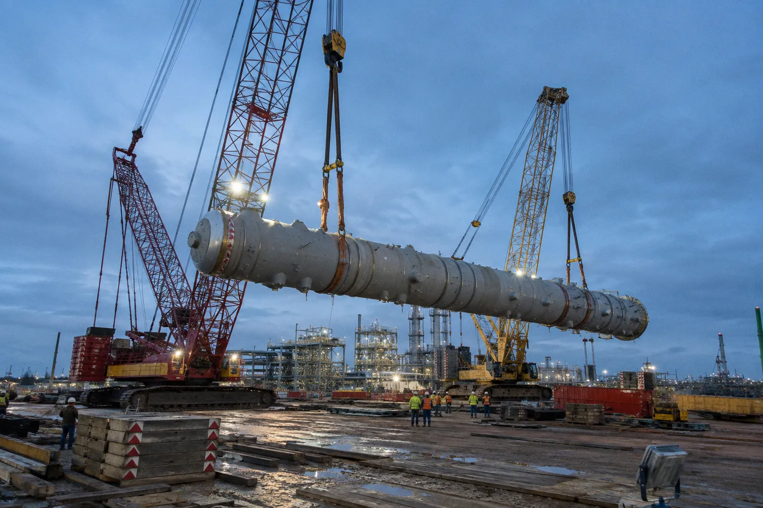
At the beginning, the tail crane may carry a substantial portion of the column weight. As the inclination angle approaches 90 degrees, that share decreases continuously. At the vertical position, the tail crane should carry no meaningful share of the suspended equipment weight in the idealized load path. The main crane assumes the full vertical load.
This change is the central mechanical problem in upending. The cranes do not simply lift the same object together. They perform different functions at different stages of the rotation.
In column upending, the critical variable is not the total weight alone. It is the changing reaction at each lifting point as the center of gravity moves through the rotation arc.
The mechanics of progressive load transfer
A typical upending operation uses two cranes:
- The main crane lifts from the top or upper lifting point and gradually raises the column.
- The tail crane controls the lower end, preventing uncontrolled sliding, lateral movement, or rotation.
- The column rotates around a changing instantaneous center as the main crane increases elevation and the tail crane controls the base.
- The load path changes continuously from a two-crane support condition to a predominantly single-crane suspension.
The tail crane is often described as a stabilizing crane. That description is incomplete. During the first part of the lift, the tail crane is also a structural support carrying a calculable portion of the column weight. Its role changes only as the geometry changes.
At 0° inclination, the column is horizontal. Its center of gravity lies between the two lifting points. The vertical reactions at the main and tail cranes depend on the position of that center of gravity relative to the distance between the lifting points.
As the main crane raises its end, the column rotates. The tail end remains close to the ground or moves under controlled guidance, depending on the selected method. The effective moment arm around the tailing point changes. The tail crane reaction therefore falls.
At 90°, the column is vertical. The main lifting point is above the center of gravity. The tailing point no longer supports the equipment weight in the ideal static model. The main crane carries the full weight of the column, subject to the effects of rigging geometry, acceleration, wind, friction, and any contact with temporary supports or the ground.
This is why a load percentage calculated only at the horizontal position is insufficient. The initial reaction is one condition. It is not the load history.
Calculating static load sharing at horizontal orientation
The first vessel upending load calculation begins with the basic geometry.
Let:
- W be the total column weight.
- L be the horizontal distance between the main and tail lifting points.
- x be the distance from the tail lifting point to the column center of gravity.
- Rₜ be the tail crane reaction.
- Rₘ be the main crane reaction.
For an ideal static, horizontal arrangement:
- Tail reaction is proportional to the distance from the center of gravity to the main lifting point.
- Main reaction is proportional to the distance from the center of gravity to the tail lifting point.
- The two reactions together equal the total weight.
Expressed as a simplified beam model:
- Rₜ = W × (L − x) / L
- Rₘ = W × x / L
The formulas are simple. Their application is not.
The center of gravity must represent the complete lifted system, not just the cylindrical shell. Platforms, ladders, trays, insulation, internals, temporary supports, lifting lugs, rigging components, and residual contents can alter the effective position of the COG. A small longitudinal shift can produce a meaningful change in the initial crane reactions when the lifting points are widely separated.
The beam analogy also assumes that the load behaves as a rigid body and that both crane lines provide the intended vertical reactions. Real equipment introduces additional variables:
- Lifting lugs may not lie in the same vertical plane.
- Sling angles can create horizontal components.
- Crane boom geometry can cause the hook to move relative to the lifting point.
- Ground contact at the tail end can introduce friction and restraint.
- The column may flex, particularly if the lifting points are not positioned for the actual stiffness distribution.
- Unequal hoist speeds can create transient load transfer.
The static calculation is therefore the starting point for the lift plan. It is not a substitute for a three-dimensional rigging and structural analysis.
A practical horizontal-load example
Assume a column has two lifting points separated by a distance L. The COG is not centered. It lies closer to the main crane, so x is greater than half of L when measured from the tail point.
The main crane will carry the larger initial reaction because the COG is farther from the tail point. The tail crane will carry the smaller reaction because the COG is closer to it.
If the COG were exactly at the midpoint, the ideal static reactions would be equal. That symmetry disappears as soon as the COG shifts. It also disappears during rotation, even if the column began with a perfectly centered COG.
The following table describes the mechanical relationship rather than a universal load chart:
| Lift condition | Main crane function | Tail crane function | Expected load behavior |
|---|---|---|---|
| 0° horizontal | Supports one end and begins the lift | Supports and controls the lower end | Both cranes carry vertical reactions determined by COG position |
| Early rotation | Raises the upper end | Controls rotation and prevents uncontrolled movement | Load begins transferring toward the main crane |
| Intermediate angle | Becomes the dominant lifting support | Maintains control with a reduced reaction | Tail crane load decreases continuously |
| Near vertical | Supports nearly all equipment weight | Controls alignment and may approach minimal vertical reaction | Main crane approaches full suspended load |
| 90° vertical | Suspends the column | No longer carries the ideal equipment weight | Main crane carries approximately 100% of the equipment weight |
The phrase “approximately 100%” matters. It refers to the ideal vertical load path. The actual crane load can be affected by dynamic effects, rigging friction, side loading, temporary contact, and the way the tailing connection is released or unloaded.
Why the load shift is continuous
The tailing lug load shift angle is governed by geometry and the selected upending method.
A column does not rotate while preserving the horizontal reaction pattern. The relative position of the center of gravity and the lifting points changes with the inclination angle. The vertical projection of the equipment weight acts through the COG, while the cranes provide reactions through their own lifting lines. The moment balance must be satisfied at every meaningful stage of the rotation.
At the start, the tail crane has a finite reaction because the tail point is part of the support system. As the main crane raises the top, the column’s weight creates a progressively different moment around the tailing point. The tail reaction decreases as the main hook assumes more of the supporting function.
This is the defining difference between column upending and a conventional tandem lift.
In a conventional tandem lift, both cranes are normally intended to maintain a planned share of the load while the object travels. The load ratio may change because of acceleration or geometry, but the operation is designed around continuing support from both cranes.
In upending, the change is intentional. The operation is designed to move from two-point support toward single-point suspension.
A tail crane that carries 40% of the initial reaction does not carry 40% throughout the lift. That percentage belongs to one geometric condition only.
The exact tail crane load variation curve depends on parameters that cannot be reduced to the rotation angle alone:
- Column length and diameter.
- Center of gravity location.
- Distance between lifting points.
- Elevation and horizontal position of each crane.
- Rigging length and sling angle.
- Tailing lug orientation.
- Whether the lower end rolls, slides, pivots, or remains suspended.
- Contact friction and ground bearing conditions.
- Hoist line movement and crane boom articulation.
For that reason, a generic curve can explain the direction of transfer, but it cannot replace a project-specific calculation. Without the structural model and rigging geometry, the exact load percentage at an intermediate angle remains unknown.
Dynamic load factors and the 1.2 multiplier
Static load sharing is necessary but incomplete. A column upending operation contains several opportunities for dynamic amplification.
The main crane may take load faster than planned if the hoist speed is not synchronized with tail crane payout. The tail crane may experience a sudden reduction in line tension when the lower end loses contact or passes through a geometric transition. A column can swing if the hook path does not follow the intended rotation center. A short stop can create shock loading in the rigging system.
Lift plans frequently include a dynamic factor such as 1.2 to provide a margin against sudden load transfer, dynamic shock, or minor unaligned movement. Applied correctly, the factor increases the design load used for crane, rigging, lifting lug, and local shell checks.
It does not mean that every crane carries 1.2 times the entire column weight at every moment. The factor is applied to the relevant calculated reaction or design condition according to the engineering basis of the lift plan.
The distinction is important:
1. Calculate the ideal static reaction at the relevant angle.
2. Identify the governing condition for each crane and lifting point.
3. Apply the specified dynamic factor to the design reaction.
4. Check crane capacity at the actual working radius and boom configuration.
5. Check the rigging and lugs for the resulting forces, including horizontal components.
6. Confirm that the support surface, travel path, and exclusion zone can accommodate the operation.
A dynamic factor is not a correction for poor control. It does not authorize abrupt hoisting, excessive line slack, uncontrolled slewing, or contact between the column and surrounding steelwork. Operational discipline remains part of the engineering control system.
Crane capacity is not rated capacity alone
A crane’s rated capacity depends on configuration and radius. During upending, the main crane radius may change as the column rises. The tail crane may experience a difficult condition even while its vertical load is falling, because the line angle or horizontal restraint can become more severe.
The lift plan therefore needs to assess:
- Maximum main crane load during the rotation.
- Maximum tail crane load before the tail reaction approaches zero.
- Main crane radius at each critical stage.
- Tail crane radius and boom geometry.
- Hook travel and potential side loading.
- Ground bearing pressure under each crane.
- Clearance from pipe racks, foundations, temporary steel, and adjacent equipment.
- The point at which the tail crane can be safely released or fully unloaded.
A crane chart should be read against the actual configuration. The nominal capacity printed for a crane model is not the operating capacity of the specific setup.
From tandem crane dynamics to vertical suspension
The phrase “tandem crane column lift mechanics” can create the wrong mental model. Upending is a tandem operation in the broad sense that two cranes are involved, but it is not a fixed-ratio tandem lift.
The load transfer follows a sequence.
1. Initial tensioning
Both cranes take up slack under controlled instructions. The purpose is to establish the intended load path before the column leaves its supports.
At this stage, the rigging should be checked for seating, line alignment, lug orientation, and unintended contact. A line that appears tensioned may still not be sharing load as assumed if the hook, shackle, or sling has shifted into a different position.
2. Main-end elevation
The main crane raises the upper end. The tail crane controls the lower end and prevents lateral movement.
The column remains a coupled mechanical system. Any difference in hoist movement changes the geometry. The tail crane should not be treated as an independent winch pulling against the main crane. Its line tension is a reaction within the rotating system.
3. Controlled rotation
As the inclination angle increases, the main crane assumes a growing portion of the vertical load. The tail crane load falls.
Operators and the lifting supervisor should monitor the actual behavior against the planned sequence. The relevant signal is not only whether the column is rotating. It is whether the line tensions, hook paths, and clearances remain consistent with the calculated model.
4. Near-vertical transition
The operation becomes sensitive near the end of the arc. The tail crane may be approaching minimal vertical reaction, but the column can still have lateral momentum or a tendency to swing.
The main crane now carries almost the entire equipment weight. The column’s center of gravity is below the primary lifting point, and the suspended system behaves differently from the early two-crane condition.
The tail crane should be unloaded according to a defined procedure. It should not be released merely because the column looks vertical. The team must confirm stability, orientation, clearance, and the absence of unintended contact.
5. Vertical stabilization
Once vertical, the main crane supports the equipment. The column may then be transferred to a foundation, temporary support, or permanent structural system.
This stage introduces a separate set of risks. The crane load can change rapidly as the base approaches the foundation, anchor bolts, temporary guides, or erection aids. Contact with a foundation does not automatically eliminate crane load. A partially supported vessel can distribute reactions through the base while retaining significant tension in the crane line.
Managing tailing lug stress during the rotation arc
The tailing lug is often discussed as though its maximum demand occurs when the tail crane carries its maximum vertical reaction. That is not always sufficient.
A lug is loaded through a combination of forces:
- Vertical reaction from the tail crane.
- Horizontal force created by sling angle.
- Local bending from eccentric connection geometry.
- Out-of-plane force caused by misalignment.
- Shock from sudden line tension.
- Shell stress around the lug attachment.
- Weld stress and load transfer into reinforcement plates.
As the column rotates, the direction of the tailing force changes relative to the lug and the vessel shell. The vertical reaction may decrease, while the local force orientation becomes less favorable. A falling crane load therefore does not prove that the lug is becoming safer.
The engineering review should cover the full rotation arc. At minimum, it should consider the horizontal starting condition, intermediate angles, the point of maximum geometric restraint, and the near-vertical condition.
The lug design should be checked for:
- Plate net-section strength.
- Shear-out and tear-out.
- Pin bearing.
- Weld capacity.
- Local shell membrane stress.
- Shell bending and ovalization.
- Reinforcement load distribution.
- Out-of-plane loading.
- Fatigue or repeated-use effects where applicable.
The connection hardware also matters. Shackles, pins, hooks, swivels, and slings must be compatible with the lug geometry. A connection that is nominally strong can still impose damaging edge contact or side loading if the load does not align with the intended plane.
Field control: what the calculation must become
A technically sound lift plan has to survive contact with the site. The calculation should be translated into observable control points.
The lifting supervisor should know:
- Which crane takes the initial load.
- What the expected initial reaction is for each crane.
- At which angles the main crane becomes dominant.
- At what point the tail crane approaches minimum vertical reaction.
- Which movement is prohibited if the column begins to swing or bind.
- How the team will stop the operation without creating a new shock load.
- When the tail crane can be unloaded.
- How the column will be restrained after reaching vertical.
The communication protocol should remain simple. One appointed signal source should control the movement. Crane operators need clear commands for hoist, lower, hold, and stop. Simultaneous movement must follow the planned sequence, not improvised visual judgment.
BIM construction simulation can support this process by showing hook paths, crane envelopes, rotation clearance, and interference with adjacent structures. It does not replace engineering calculations. A visually correct animation can still contain an incorrect COG, an unrealistic rigging angle, or an invalid crane capacity assumption.
The model is useful when it is tied to verified project data:
- As-built column weight.
- Confirmed COG.
- Actual lifting lug coordinates.
- Crane configuration.
- Ground levels and bearing capacity.
- Temporary works and exclusion boundaries.
- Foundation elevation and final orientation.
A structural review before the lift
The final review should be concise but specific. The following points address the mechanics that most often control the operation:
- Confirm the total lifted weight, including rigging and temporary attachments.
- Confirm the center of gravity from the current equipment configuration.
- Calculate the initial main and tail reactions from the actual lifting-point geometry.
- Analyze the load transfer across the 0° to 90° rotation arc.
- Apply the specified dynamic factor, including the commonly used 1.2 factor where required by the lift basis.
- Check crane capacity at the maximum working radius and configuration.
- Check the tailing lug and shell reinforcement at intermediate angles, not only at the starting position.
- Check sling angles, shackle orientation, pin bearing, and possible side loading.
- Verify ground bearing and crane mat arrangement.
- Define the tail crane unloading point and procedure.
- Establish stop criteria for line shock, unexpected contact, loss of clearance, abnormal deflection, or deviation from the planned hook path.
- Confirm the vertical stabilization and foundation transfer sequence.
The central conclusion is mechanical rather than procedural. Column upending is a progressive load-transfer operation. The tail crane begins as a significant support, then becomes a control device as the main crane takes over. The load does not remain divided in a fixed proportion, and the tail crane does not carry half of the column throughout the rotation.
A correct design follows the reactions through the entire arc. It treats the crane loads, lifting lugs, rigging, hook paths, and temporary supports as one changing system. That is the difference between a tandem lift described in general terms and an upending plan that reflects the actual mechanics of the column.