Slip-Critical vs Bearing Bolts in Industrial Frames
The difference between slip-critical and bearing-type bolted joints is not the bolt itself. It is the intended load-transfer mechanism.
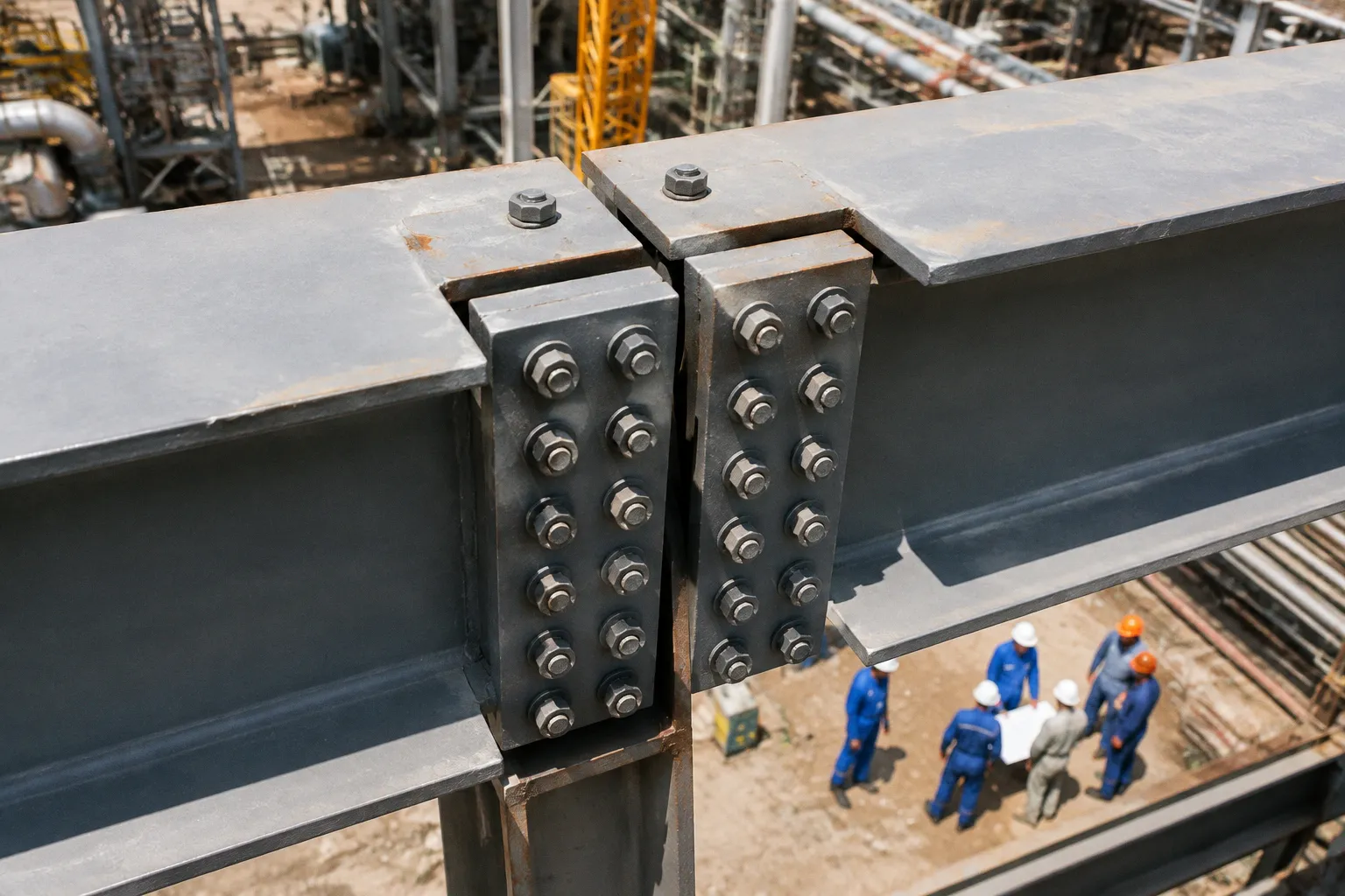
Slip-Critical vs Bearing Bolted Joints in Steel Frames
In a bearing-type connection, the joint is allowed to experience limited movement as the bolt shank bears against the edge of the hole. The applied force is then carried through bolt shear and plate bearing. In a slip-critical connection, the design objective is different: high-strength bolts are pretensioned so that friction between the connected surfaces resists service loads before the joint can move.
This distinction controls the required bolt installation, the treatment of the faying surfaces, the inspection method, and the consequences of any slip. It is especially important in industrial frames, pipe-rack structures, equipment supports, crane-related steelwork, and modular petrochemical assemblies where vibration, fatigue, alignment, and repeated load reversals can govern the connection behavior.
Load transfer: bearing against the hole or friction across the joint
A structural steel bolted connection contains several mechanical interfaces:
- the bolt shank and the bolt hole;
- the connected plates or angles;
- the contact surfaces between those plates;
- the bolt head, nut, and washer assemblies;
- the surrounding material that transfers force into the joint.
The connection classification depends on which of these interfaces is expected to carry the design load during service.
Bearing-type connections
A bearing-type joint transfers force directly through the bolt and the connected material. The bolt resists shear. The plate resists local bearing at the hole. If the applied force is large enough to overcome the initial clearance between the bolt and hole, the bolt contacts the hole edge and the joint develops bearing action.
That contact is not automatically a defect. It is the expected behavior of a bearing connection.
Before contact occurs, a small amount of joint movement may be possible. The magnitude depends on hole clearance, fabrication tolerances, bolt alignment, and the stiffness of the connected components. Once the bolt bears against the hole, the connection continues to transfer load through bolt shear and plate bearing, provided the design capacities are not exceeded.
The engineering checks therefore focus on the relevant limit states. These may include:
- bolt shear;
- bolt tension, where the joint is also tension-loaded;
- plate bearing at the bolt hole;
- tear-out or edge failure;
- net-section rupture;
- block shear;
- local yielding or distortion of the connected elements.
The phrase “bearing-type” does not mean that the joint is weak or poorly controlled. It means that movement into bearing is part of the design model.
Slip-critical connections
A slip-critical joint is designed to prevent movement at the faying surfaces under the specified service conditions. The applied force is resisted by friction created when high-strength bolts compress the connected plates through pretension.
The bolt is not functioning primarily as a dowel in the initial load-transfer stage. Instead, its pretension produces a clamping force. That clamping force acts across the faying surfaces. The available slip resistance depends on the pretension, the number of effective interfaces, the geometry of the joint, and the slip coefficient of the surfaces.
The joint must therefore be treated as a controlled friction system. A bolt installed to a nominally similar appearance is not enough. The actual behavior depends on whether the required pretension was achieved and whether the contact surfaces retain the friction characteristics assumed in design.
This matters in industrial steelwork for several reasons. Relative movement may damage attached piping, alter equipment alignment, amplify vibration, or create cyclic movement in secondary members. In a frame carrying sensitive machinery, eliminating service slip can be more important than maximizing the nominal static shear capacity of the bolts.
A slip-critical joint is not defined by the label on the bolt. It is defined by the combination of pretension, surface condition, and the required no-slip performance.
The practical comparison
| Parameter | Bearing-type connection | Slip-critical connection |
|---|---|---|
| Primary load-transfer mechanism | Bolt shear and plate bearing after contact | Friction between pretensioned faying surfaces |
| Intended service movement | Limited slip may be permitted | Slip is prevented under the specified service load |
| Bolt installation | Bolts are installed according to the specified snug-tight or pretensioned procedure | High-strength bolts require controlled pretensioning |
| Surface requirement | Surface condition remains relevant to fit-up and durability but is not normally the governing friction parameter | Faying surfaces must meet the specified slip-coefficient class |
| Main design concern | Shear, bearing, tear-out, rupture, and related limit states | Slip resistance first, followed by applicable strength limit states |
| Effect of overload slip | Not applicable as a transition; bearing is the intended mechanism | Joint can transition into bearing behavior after slip |
| Typical sensitivity | Hole geometry, edge distances, plate thickness, bolt shear strength | Pretension, surface preparation, coating compatibility, inspection |
| Field risk | Incorrect bolt grade or installation can reduce strength | Uncontrolled coating or inadequate pretension can invalidate the assumed slip resistance |
The distinction should appear clearly in the design drawings and connection schedule. If the drawings merely identify high-strength bolts without stating the required joint behavior, the field team may install a connection that looks correct but does not perform as designed.
Faying surfaces determine the slip coefficient
The faying surface is the area where two connected steel surfaces come into contact and transfer frictional force. Its condition is not a finishing detail. In a slip-critical joint, it is a design variable.
The relevant property is the slip coefficient, commonly denoted by μ. A higher coefficient means that a given level of bolt pretension can produce greater slip resistance, assuming the rest of the connection geometry is unchanged.
The research basis provided for this comparison identifies two AISC surface classes:
- Class A: unpainted clean mill scale, with a slip coefficient of 0.30;
- Class B: blast-cleaned bare steel or zinc-rich coatings, with a slip coefficient of 0.50.
The difference is substantial. A surface assigned μ = 0.50 does not behave like one assigned μ = 0.30. The coating system, surface preparation, contamination, and installation sequence must match the design assumption.
Why ordinary paint creates a problem
Industrial steel is often fabricated, transported, stored, primed, and assembled in stages. Each stage can alter the faying surfaces. A primer applied for corrosion protection may be acceptable on exposed steel but unsuitable between plates in a slip-critical joint. The same is true of overspray, welding residue, oil, dirt, excessive mill scale, or a coating whose friction performance has not been established for the intended connection.
The problem is not simply that paint makes steel smooth. The problem is that the design calculation assumes a defined interface. If the actual interface differs, the assumed friction resistance may not exist.
A standard unapproved primer should not be treated as interchangeable with a qualified zinc-rich coating. The coating must be compatible with the specified slip coefficient and the applicable project requirements. A surface that looks clean to the eye may still be unsuitable if its preparation does not match the connection specification.
For large pipe-rack assemblies and shop-fabricated modules, this requires coordination between design, detailing, coating, and erection. The faying surface condition must be preserved through handling. A surface prepared in the fabrication shop can be contaminated during transport or damaged by temporary fit-up operations before the final bolts are installed.
Surface condition is part of the connection record
For a bearing-type joint, the condition of the contact surfaces usually does not control the primary shear mechanism. For a slip-critical joint, it can control the first limit state reached in service.
A connection review should therefore identify:
- the specified faying-surface class;
- whether the surfaces are bare, blast-cleaned, or coated;
- whether the coating is permitted in the faying interface;
- how the surfaces will be protected during transport and erection;
- how damaged or contaminated areas will be repaired;
- what inspection evidence confirms compliance.
This is a mechanical chain. If the surface preparation changes, the friction coefficient changes. If the friction coefficient changes, the slip resistance changes. The connection cannot be evaluated independently of its surface treatment.
High-strength bolts and pretensioning protocols
ASTM F3125 includes commonly specified structural bolt grades such as Grade A325 and Grade A490. Their ultimate tensile strengths are identified as 120 ksi, or approximately 830 MPa, for A325 and 150 ksi, or approximately 1040 MPa, for A490.
These values describe bolt material strength. They do not by themselves establish that a joint is slip-critical. A high-strength bolt can be used in a bearing-type connection. Conversely, a slip-critical connection requires more than the nominal strength grade. It requires the specified pretension and the correct installation procedure.
Pretension is a controlled installation condition
Pretension compresses the connected parts. The resulting clamping force generates friction at the faying surfaces. The installation process must produce the required bolt tension consistently across the joint.
The specific method may be defined by the project specification and applicable structural steel standard. Common controlled approaches include calibrated wrench procedures, turn-of-nut installation, tension-control bolts, and direct-tension indicators. The selected method must be compatible with the bolt assembly, access conditions, and inspection plan.
The critical point is repeatability. A pretensioned joint is not complete because the nut has been tightened visually or because the bolt is difficult to turn. The installation procedure must provide a verifiable relationship between the specified method and the achieved pretension.
The sequence also matters. Tightening one bolt to final pretension before the surrounding bolts are engaged can alter the force distribution as the plates draw together. For this reason, installation commonly proceeds in stages, bringing the joint into contact before final pretensioning. The exact sequence depends on the connection geometry and the governing specification.
Pretension does not replace fit-up control
High bolt pretension cannot correct every fabrication error. Oversized gaps, misaligned holes, warped plates, excessive burrs, or forced fit-up can create local stress and uneven contact. A slip-critical connection depends on effective contact over the intended faying area. If the plates touch only at isolated points, the friction system is not uniform.
The hole pattern must allow the bolt group to be assembled without damaging the steel or forcing the plates into an unintended position. Reaming, drifting, and corrective work must follow the project requirements. Field modifications that alter hole geometry can affect both the bolt capacity and the contact condition.
This is particularly relevant for heavy industrial frames. Members may be large, stiff, and difficult to move after lifting. A small detailing error at a shop connection can become an erection problem when the assembly is suspended, aligned, and connected at elevation. The result may be a joint that reaches pretension while still carrying unintended distortion.
Avoiding bolt-selection ambiguity
AISC guidance recommends maintaining a minimum 1/4-inch difference in diameters when different bolt sizes are used on the same project. It also recommends avoiding two different grades, such as A325 and A490, at the same bolt diameter. The purpose is practical: reduce field installation errors.
If two bolt grades share the same diameter and similar visual appearance, the installer may not distinguish them reliably in a complex assembly. The wrong grade can be placed in a connection with a different pretension or strength requirement. A clear bolt schedule, distinct markings, controlled storage, and disciplined material tracking reduce this risk.
This is not administrative excess. Bolt identification is part of load-path control.
In a pretensioned connection, installation quality is a structural variable. The design assumption ends where uncontrolled field practice begins.
What happens when a slip-critical joint slips
Slip-critical design prevents movement under the specified service conditions. It does not create an infinitely rigid joint, and it does not mean that a single slip event automatically causes structural collapse.
If the applied load exceeds the available slip resistance, the faying surfaces can move relative to one another. The bolt then contacts the edge of the hole. From that point, the joint reverts to bearing-type behavior: the load is transferred through bolt shear and plate bearing.
This transition must be understood correctly.
The initial slip may affect alignment, vibration, fatigue performance, or attached systems even if the remaining bearing capacity is adequate. In a petrochemical pipe rack, a small movement at a primary connection can influence the position of pipe shoes, guides, clamps, or equipment nozzles. In a machinery support, the structural member may remain stable while the operational behavior becomes unacceptable.
The engineering question is therefore not simply whether the connection survives after slip. It is whether slip is acceptable for the structure’s function, serviceability, fatigue environment, and attached systems.
Slip is not the same as bolt fracture
These are different failure or response mechanisms:
1. Slip: relative movement occurs at the faying surfaces because the applied load exceeds the available friction resistance.
2. Bearing: after movement, the bolt contacts the hole and transfers force through shear and plate bearing.
3. Bolt shear or tension failure: the bolt reaches its relevant strength limit.
4. Plate failure: the connected material reaches bearing, tear-out, net-section, block-shear, or other limit states.
5. Fatigue damage: repeated stress ranges cause progressive deterioration, depending on the detail and loading history.
A slip event can be serviceability-critical without being an immediate strength collapse. The reverse is also true: a connection can have adequate nominal strength but be poorly suited to a structure where movement is unacceptable.
The choice between connection types must therefore be linked to the load case. Static gravity shear in a conventional frame may be compatible with bearing behavior. Reversing loads, vibration, fatigue, impact, or strict alignment requirements may justify slip-critical design.
Choosing the connection type in an industrial frame
The correct connection is determined by the structural behavior required, not by a general preference for one bolt type.
Bearing-type connections are often appropriate when
A bearing connection can be effective where limited initial movement does not impair the structure or attached systems. The design can directly account for bolt shear and plate bearing. Fabrication and erection procedures remain important, but the connection is less dependent on a precisely maintained friction interface.
This may suit ordinary beam-to-column shear connections, bracing joints, and other locations where the governing design checks are strength-based and service slip has no unacceptable consequence. The actual choice remains project-specific. A bearing joint still requires correct bolt grade, hole geometry, edge distance, plate thickness, and installation.
Slip-critical connections become more relevant when
Slip resistance is generally more important when movement at the joint can produce a secondary problem. Examples include:
- connections subject to significant vibration or repeated load reversals;
- fatigue-sensitive industrial structures;
- crane-supporting or impact-loaded frames;
- joints supporting rotating equipment or sensitive machinery;
- connections where bolt-hole movement would disturb alignment;
- modular assemblies connected to piping, equipment, or other rigid systems;
- joints where serviceability movement is more restrictive than ultimate strength.
These applications should not be reduced to a slogan. A slip-critical designation introduces additional requirements. The design team must define the slip condition, the faying-surface class, the coating system, the bolt assembly, the pretensioning method, and the inspection process.
The connection can be structurally adequate but operationally wrong
Industrial structures are integrated systems. A steel frame may carry its design load while causing problems elsewhere. Relative movement can be transmitted into piping supports, access platforms, equipment bases, cladding, or fireproofing. Vibration can increase noise and fatigue demand. Misalignment can complicate module installation or maintenance.
This is why the connection decision should include more than the calculated bolt capacity. The review should ask what movement is permitted at the joint and what components are connected to it.
A compact engineering comparison is useful:
| Question | Bearing-type answer | Slip-critical answer |
|---|---|---|
| Can the joint move before full bearing develops? | Yes, within the clearance and connection behavior | The design seeks to prevent this under service loads |
| What carries the load initially? | The joint develops bolt-hole contact and bearing action | Friction generated by bolt pretension |
| What must remain controlled in the field? | Bolt installation, hole quality, fit-up, and material grade | All bearing-type controls plus pretension and faying-surface condition |
| What happens after overload? | Bearing behavior is already part of the design basis | Slip may occur, followed by bearing behavior |
| What is the main hidden risk? | Local plate or bolt limit states | Loss of friction due to inadequate pretension or unsuitable surfaces |
Field installation errors that change the design behavior
The most common problems are not theoretical. They occur at the interface between drawings, fabrication, coating, logistics, and erection.
Coating the wrong surface
A connection specified as slip-critical can lose its assumed performance if the faying surfaces receive a coating that was not included in the design. This includes ordinary primer, uncontrolled touch-up paint, or repair coating applied after blasting.
The remedy is not to rely on visual inspection. The approved coating system and repair procedure must explicitly address the faying surface. If the surface condition changes, the responsible engineer must determine whether the slip coefficient assumption remains valid.
Mixing bolt grades
A325 and A490 bolts may look similar in the field, especially when stored in mixed containers or transferred between erection crews. Using two grades at the same diameter increases the chance of substitution. Clear procurement, tagging, storage, and installation controls are more effective than asking an installer to identify every bolt by memory.
Pretensioning without a defined method
A worker may tighten a bolt until the nut appears fully seated. That does not establish the required pretension. A slip-critical joint needs a specified and inspectable installation process. The method must be available to the erection crew before work begins, not introduced after a failed inspection.
Contaminating the faying surfaces
Oil, mud, moisture, weld spatter, scale, and handling damage can alter the interface. The risk increases on large modules that remain exposed during transport or are assembled in variable weather. Surfaces need protection and inspection immediately before the joint is closed.
Treating every high-strength bolt as slip-critical
This reverses the logic. High-strength bolts are components. Slip-critical behavior is a connection design condition. The presence of an A325 or A490 bolt does not prove that the joint is designed to resist slip through friction.
The drawings should state the intended joint behavior and the installation requirements in a way that can be followed without interpretation. If the specification is ambiguous, the field will fill the gap with habit.
A mechanical review sequence for designers and inspectors
A useful review can follow the actual load path rather than starting with the bolt catalog.
1. Define the service requirement.
Determine whether limited joint movement is acceptable. Include vibration, fatigue, impact, alignment, and the behavior of attached piping or equipment.
2. Identify the design mechanism.
State whether the joint is bearing-type or slip-critical. Do not infer the classification from the bolt strength grade alone.
3. Check the connected material.
Review plate thickness, hole geometry, edge distances, net section, block shear, bearing resistance, and the possibility of local distortion.
4. Select the bolt assembly.
Confirm the applicable grade, diameter, washer and nut requirements, markings, and material-control procedure. Avoid unnecessary grade ambiguity.
5. Establish the faying-surface condition.
Specify the surface class, preparation method, coating compatibility, and treatment of damaged or contaminated areas.
6. Define pretensioning and inspection.
Identify the permitted installation method, the sequence, calibration requirements where applicable, and the records needed to verify completion.
7. Review the erection sequence.
Confirm that the crew can assemble the joint without forced fit-up, excessive drifting, plate damage, or loss of surface preparation.
8. Evaluate the post-slip condition where relevant.
For a slip-critical joint, determine the consequences if service slip occurs and verify the applicable bearing and strength limit states.
9. Coordinate with adjacent systems.
Check whether movement at the steel connection can affect pipes, equipment, platforms, cladding, fire protection, or maintenance access.
10. Close the documentation loop.
The final record should connect the approved design, bolt certificates, surface treatment, installation method, inspection results, and any field changes.
This sequence is deliberately mechanical. It follows the chain from required behavior to physical interface to field verification.
The decision is about movement, not prestige
Slip-critical joints are not automatically superior. They are more controlled because the design depends on a controlled friction interface. That control has a purpose when joint movement is unacceptable or when service conditions make slip consequential.
Bearing-type joints are not automatically inferior. They use a different load-transfer model. When movement into bearing is acceptable and the strength limit states are satisfied, they can be a rational and efficient solution.
The wrong connection is not the one with the lower theoretical sophistication. It is the one whose actual field behavior does not match the design assumption.
For industrial frames, the final decision should be clear on five points:
- what load-transfer mechanism is intended;
- whether slip is permitted during service;
- what surface condition is required;
- how bolt pretension will be achieved and verified;
- what the joint can sustain if the intended mechanism changes.
If those points are explicit, the choice between slip-critical and bearing bolted joints becomes an engineering decision. If they are left implicit, the connection is governed by assumptions made during fabrication and erection. That is an avoidable form of structural uncertainty.