Tail Crane vs Tailing Frame: When to Choose Each
In a heavy lift, the difficult moment is often not the final placement. It is the transition: a long vessel or column leaving the horizontal position, passing through an unstable geometry, and arriving upright while the load path changes continuously.
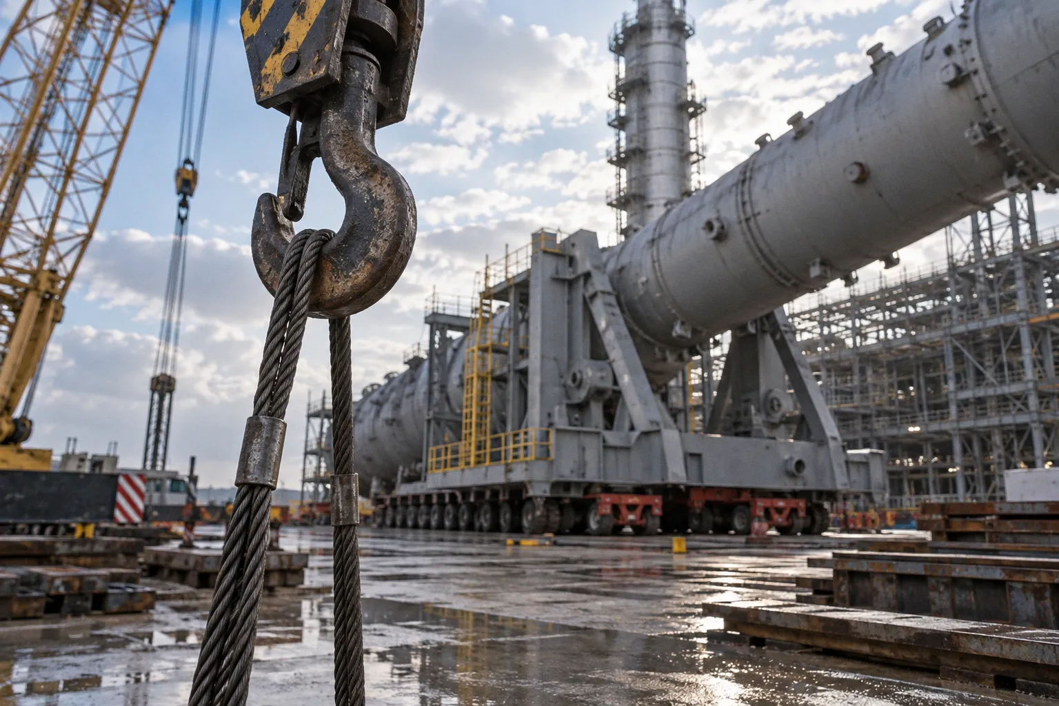
The choice between a tail crane and a tailing frame determines how that transition is controlled.
This is why the question of tail crane vs tailing frame heavy lift should not be reduced to rental price or nominal lifting capacity. Both methods can support vessel erection and column upending, but they manage the bottom of the load in fundamentally different ways. One relies on a second crane and active coordination between operators. The other uses a designed mechanical interface, usually combined with an SPMT or skid system, to guide the tail through a planned path.
The right choice comes from the relationship between the load, the ground, the available space, the crane fleet and the changing center of gravity—not from the equipment name alone.
Two-Crane Tailing Operations
A tail crane operation is a two-crane upending method. The main crane controls the top end of the vessel or column, while the tail crane supports and controls the lower end during the initial rotation. The load begins horizontally, with both cranes carrying defined portions of the reaction forces. As the main crane raises its end, the tail crane lowers, pays out or repositions in a controlled sequence so that the bottom of the load moves along the required path.
The tail crane is not simply a smaller version of the main crane. Its function is different. It must control the tail without allowing the lower end to swing, drag, lift unexpectedly or move outside the approved geometry. Depending on the configuration, the tail crane may work with a hook, lifting beam, tailing lug or another engineered connection. The connection must be designed for the changing angle and the possibility of side loading or unintended contact.
The operation continues until the vessel reaches a stable vertical position or until the main crane has taken the full working load. At that point, the tail crane is released according to the method statement, and the main crane completes the placement or transfers the load to another support system.
Tailing is not the same as tandem lifting
The distinction matters because the two terms are often used interchangeably in project discussions.
Tailing describes a specific movement of the load, usually the controlled rotation of a horizontal vessel, column or module toward a vertical orientation. The second crane manages the tail while the main crane raises the opposite end. Rotation and the changing position of the lower end are central to the operation.
Tandem lifting describes a load-sharing arrangement in which two cranes lift one load together. The cranes may raise, lower or position the load while maintaining coordinated control, but the operation does not necessarily involve rotation from horizontal to vertical. A tandem lift can be a direct vertical pick, a translation across a site, or a placement between supports. It may involve two cranes without being a tailing operation.
A two-crane tailing operation can therefore be considered a particular type of coordinated two-crane lift, but it should not automatically be planned or described as an ordinary tandem lift. The load path, crane roles, connection points and control sequence are different. Treating the two as identical can hide the most important engineering issue: during upending, the load reactions and geometry change continuously.
Tailing is not merely two cranes lifting together. It is a controlled rotation in which the lower end of the load has its own movement, reaction and risk profile.
How the load behaves during the rotation
At the beginning of an upending operation, the tail crane may carry a substantial vertical reaction. As the main crane raises the top end, the contact and lifting conditions at the tail change. The lower end may need to descend, travel or rotate while the main hook load increases. The exact force distribution depends on the vessel geometry, rigging arrangement, lifting points, center of gravity, crane radii and the planned motion.
A tail crane operator cannot treat the job as a simple lowering exercise. A small error in boom movement, hoist speed or crane position can create a sudden change in sling angle or side load. The main crane and tail crane must follow the same movement plan, with clear communication and agreed stop signals. The operation also requires a defined response if the load pauses, the SPMT or support surface changes condition, a crane approaches a limit or the vessel does not follow the expected path.
The practical strengths of the tail crane method are clear:
- It can provide active control over the lower end of the load.
- The crane position can sometimes be adjusted during the operation.
- A suitable crane already working on the project may be used without introducing a separate mechanical frame.
- The method can adapt to a less linear path when the site geometry requires controlled changes in direction.
But this flexibility comes with a wider operational footprint. Two cranes need separate working zones, exclusion areas and access for setup. The tail crane may require substantial outrigger reactions even when it is carrying less of the total load than the main crane. Its maximum radius, boom configuration and ability to maintain a safe connection to the tail must be checked throughout the entire sequence, not only at the starting position.
Tailing Frame Engineering: Pivot Points and SPMT Integration
A tailing frame approaches the same problem from another direction. Instead of suspending the lower end from a second crane, the frame creates a controlled mechanical connection between the vessel base and a transport or sliding system.
The frame is usually connected to the vessel’s base skirt, lower shell or another structurally verified attachment area. Its geometry includes one or more pivot locations that allow the lower end to rotate while the frame travels along the ground or on an SPMT. The main crane lifts the top end. The tailing frame guides the bottom end, carrying reactions through its structure, wheels, skid shoes or transporter interface.
This arrangement can make the load path more predictable, but only if the frame and its connections are designed for the complete upending sequence. The vessel shell may be adequate for lifting from its top lugs and still require reinforcement at the base where the tailing frame is attached. Local shell stresses, skirt distortion, weld details, temporary stiffening and load introduction points all need to be addressed before the equipment reaches the site.
Pivot points and changing geometry
A tailing frame is not just a trolley with a hinge. Its pivot arrangement determines how the vessel rotates and how the reactions move through the system.
Some designs use a primary pivot for the initial stage of rotation and a secondary pivot or engagement point as the geometry changes. The purpose is to avoid an abrupt transfer of load when the center of gravity moves relative to the support. Other designs use a fixed pivot with a guided travel path, depending on the vessel dimensions, required rotation and transporter configuration.
The frame must account for:
- The distance between the vessel’s center of gravity and the pivot axis.
- The changing vertical and horizontal reactions during upending.
- The required travel of the lower end.
- Clearance between the skirt, frame, transporter and ground.
- The possibility of temporary compression or tension in the attachment.
- The final condition in which the vessel becomes vertical and the main crane takes the dominant load.
The phrase “dual pivot” should not be treated as a universal feature or an automatic safety advantage. It describes one possible engineering arrangement. Its value depends on the actual load path and on whether the pivot transition is synchronized with the main crane movement and transporter travel.
SPMT integration
An SPMT can provide the mobility required for the tailing frame to travel as the load rotates. The transporter is not merely carrying the dead weight of the frame. It may also be exposed to horizontal reactions, uneven loading between axle lines, steering corrections and changing center-of-gravity effects. The SPMT configuration must therefore be checked for the complete sequence.
The travel path should be prepared as carefully as a crane pad. A distributed wheel load is not the same as an insignificant load. Weak subgrade, voids, trenches, underground utilities, drainage channels or abrupt changes in elevation can affect the transporter and the frame. The path needs sufficient bearing capacity, suitable grading and enough width for steering and clearance.
An SPMT-based tailing frame also introduces a different operational discipline. The travel speed, steering commands and crane hoisting rate must be coordinated. The transporter should not advance faster than the planned movement of the top end, and the crane should not force the frame into a position that the transporter cannot safely reach. The method may reduce the need for a second crane, but it does not remove the need for synchronized control.
A tailing frame replaces a second lifting machine with a designed load path. The engineering becomes more concentrated, not less important.
Evaluating Site Constraints: Ground Bearing and Spatial Limits
The site often decides the issue before the commercial comparison begins. A tail crane and a tailing frame may have similar headline lifting objectives, yet require completely different ground conditions and movement envelopes.
Ground bearing and outrigger reactions
A tail crane transfers force through outriggers, crawler tracks or another concentrated support arrangement. The reaction at each support point can be significant, particularly when the crane is working at radius or when the load moves away from the crane centerline. The ground must be assessed for bearing capacity, settlement, sliding resistance and the risk of differential movement between support points.
Temporary mats can help distribute the reaction, but mats do not solve every ground problem. They need a stable layer beneath them, and they do not compensate for voids, soft pockets or uncontrolled water conditions. If ground improvement is required, it may affect both the schedule and the feasibility of using a second crane.
A tailing frame on an SPMT distributes its reaction over multiple wheel lines. This can reduce local pressure compared with an outriggered crane, but it does not mean the system can travel over unprepared ground. The total moving load may be considerable, and the load distribution can change during rotation. The critical location may be a short section of the route where the subgrade is weaker or where the transporter passes near an underground structure.
The engineering question is not simply which method has lower pressure. It is where the pressure is applied, how it changes during the lift and whether the site can maintain the required support condition for the full travel path.
Space, clearance and movement envelope
A tail crane needs room for its own setup, boom movement, counterweight, swing radius and access. It also needs a safe separation from the main crane, the load, existing structures and personnel exclusion zones. The two cranes must be positioned so that their working radii remain acceptable throughout the operation, not only at the starting point.
This can become difficult in a congested process plant. Pipe racks, columns, cable routes, foundations, temporary buildings and overhead lines may leave no practical position for the tail crane. Even if the crane can physically reach the tail, its counterweight swing or boom clearance may conflict with adjacent assets.
A tailing frame and SPMT usually require a more defined route. The lower end of the vessel must travel along a planned path, and the transporter needs enough space to steer, correct its position and stop safely. The path may be more compact than the combined footprint of two cranes, but it must be clear and sufficiently regular. A frame is not automatically the better choice in a tight site if the tail has nowhere to travel.
The geometry should be reviewed in plan and elevation. A route that appears open from above may still fail because of an overhead pipe rack, a temporary brace, a foundation step or inadequate clearance when the vessel passes through an intermediate angle.
| Constraint factor | Two-crane tailing operation | Tailing frame with SPMT or skid |
|---|---|---|
| Primary control method | Main crane raises the top; tail crane controls the lower end | Main crane raises the top; frame and transporter guide the lower end |
| Ground demand | Concentrated reactions at outriggers or crawler tracks | Distributed wheel or skid reactions along a prepared path |
| Spatial requirement | Separate crane setup areas, swing zones and exclusion zones | Defined travel corridor plus main-crane working area |
| Movement flexibility | Can allow controlled crane repositioning where the plan permits | Usually favors a planned, relatively direct travel path |
| Main coordination issue | Synchronization between two crane operators and rigging teams | Synchronization between crane, transporter and frame movement |
| Typical engineering focus | Crane capacity at changing radii, ground reactions and tail connection | Frame strength, pivots, transporter loading and vessel attachment |
| Site sensitivity | High near structures that restrict a second crane | High where the travel path is obstructed or uneven |
Logistics and Cost Factors in Equipment Mobilization
The commercial comparison is often presented as a choice between hiring a second crane and renting a tailing frame. That is a useful starting point, but it is not the full cost picture.
A tail crane may be financially attractive when an appropriate crane is already on site. The project can use an existing asset, existing operators and an established maintenance or fueling arrangement. The additional work may involve only rigging, engineering verification and a planned shift in the crane’s schedule.
That advantage disappears if the second crane must be brought in specifically for one upending operation. Transport, assembly, counterweights, permits, operator availability, ground preparation, standby time and demobilization can all become part of the actual cost. The crane may also need to remain on site longer than the lift itself because weather, preceding work or commissioning activities affect the schedule.
The capacity of the tail crane should not be selected by looking only at the initial tail reaction. The crane must remain suitable through the critical stages, including its operating radius, hook height, boom configuration, rigging angle and any planned movement. A crane that is adequate at the beginning may be unsuitable later if the tail moves beyond its safe working envelope.
A tailing frame has a different cost profile. It may require design, fabrication or adaptation, inspection, transport, assembly and connection to the vessel. If the frame is a rental unit, its availability and compatibility with the specific vessel still need to be confirmed. The SPMT or skid system also brings its own mobilization and operating costs.
The potential advantage is that one large main crane and one compact tailing system may be easier to move and coordinate than two cranes with separate support arrangements. A modular frame can be transported in sections, and some designs are intended to fit within standard heavy-transport or container logistics. That benefit should be verified for the actual frame, rather than assumed from a generic equipment description.
The meaningful comparison should include the entire lift system:
1. Engineering and design: temporary attachments, lifting lugs, frame checks, transporter configuration, ground assessment and lift planning.
2. Mobilization: transport, permits, assembly, counterweights, mats, SPMT modules, skidding equipment and support crews.
3. Operating time: setup, trial movements, execution, pauses, inspections and demobilization.
4. Site impact: access roads, ground improvement, removal or protection of obstacles and restrictions on other construction activities.
5. Contingency: weather, equipment standby, rework of the travel path and the possibility of a delayed lift window.
A lower equipment rental rate can be outweighed by a difficult route or a long setup. Conversely, a specialized tailing frame may look expensive in isolation but reduce the number of heavy transports, shorten the preparation period and keep the site available for other work.
Managing Center of Gravity Transitions During Upending
The center of gravity is the quiet source of many upending difficulties. As a vessel rotates, its center of gravity follows a changing path relative to the crane hook, the pivot, the base and the ground. The load does not behave like a rigid object whose weight simply moves from one support to another at a constant rate.
The main crane hook load changes as the vessel rises. The tail reaction changes as the lower end moves. Sling angles change, and the horizontal component of the forces may increase or decrease depending on the stage of rotation. Near intermediate positions, the geometry can become more demanding than either the starting or final position.
A reliable method statement should identify the critical stages rather than describe the lift only as “horizontal to vertical.” For each stage, the lift team needs to understand:
- The position of the center of gravity.
- The expected main crane load and radius.
- The tail reaction or frame reaction.
- The angle and length of the rigging.
- The location of the lower end.
- The available clearance.
- The condition under which the movement must stop.
Center-of-gravity control with a tail crane
With a tail crane, center-of-gravity management is performed through coordinated crane movement. The main crane raises at a controlled rate while the tail crane lowers or travels according to the engineered sequence. The two machines must avoid creating a condition in which the tail crane is unexpectedly lifted, overloaded or pulled sideways.
The operators are not trying to keep the load statically balanced at every instant. They are following a planned transfer of reactions. That transfer needs to remain within the allowable limits of both cranes and the lifting accessories.
The control problem becomes more demanding if the cranes have different response characteristics. Hoist speeds, boom movement, braking response and operator visibility may not match. The lift director or appointed person must establish one command structure, one movement sequence and a clear rule for stopping both cranes. Independent corrections by two operators can turn a small deviation into a larger dynamic movement.
The tail connection is another critical point. A sling or lifting lug that works well at the starting angle may be exposed to an unfavorable angle later. The connection must be suitable for the full range of movement, including the possibility of contact with the vessel or frame.
Center-of-gravity control with a tailing frame
A tailing frame manages the lower end through its pivot and travel geometry. The SPMT or skid system moves as the main crane lifts, allowing the tail to follow a defined path. This can reduce the number of variables that must be controlled manually, but it does not eliminate dynamic behavior.
The frame can constrain the tail, which is useful when the vessel must follow a precise route. At the same time, a constrained system can introduce forces if the transporter moves out of alignment or if the vessel tries to follow a different path from the frame. Steering, speed and crane movement must be coordinated so that the frame is neither pushed into the load nor pulled away from it.
The transition between pivot points, if the design uses more than one, deserves particular attention. The load should not experience a sudden engagement, impact or release of support. The sequence must define how the new pivot becomes active, what reaction is expected and how the transporter responds at that moment.
The frame also has to remain stable as the vessel approaches vertical. The reaction may shift from a moving tailing condition toward a final support condition. The installation team needs to know when temporary restraints, guide structures or foundation supports become responsible for the load.
Choosing Between the Two Methods
The choice becomes clearer when the project team compares the complete operating systems rather than the equipment labels.
A two-crane tailing operation is often a strong option when:
- A suitable secondary crane is already available on the project.
- The site has enough room for two cranes and their exclusion zones.
- The ground can support the expected outrigger or track reactions.
- The lower end must be actively controlled through a variable or non-linear path.
- The lift team has the operators, supervision and communication system required for synchronized crane work.
- The vessel has verified tailing points that can accept the changing forces.
A tailing frame with an SPMT or skid system may be more suitable when:
- Bringing in a second crane would create a disproportionate mobilization burden.
- Outrigger reactions are difficult to support, while a prepared travel path is feasible.
- The site has a compact crane area but enough room for the tail to travel.
- The vessel and its base connection can be engineered for the frame reactions.
- A repeatable, guided movement is more valuable than the positional flexibility of a second crane.
- The project already has SPMT capability or a compatible transporter arrangement.
Neither list is a substitute for the lift study. A tailing frame is not automatically safer because it uses less crane equipment, and a tail crane is not automatically more adaptable because it can move independently. Safety comes from a load path that remains understood and controllable at every stage.
The project team should review the lifting arrangement in the same sequence in which the load will move. Start with the vessel on its supports. Follow the first lift, the first change in reaction, the most demanding intermediate angle, the movement of the tail and the final vertical position. Then review what happens if the lift pauses at each stage. That exercise often reveals more than comparing nominal capacities.
The best upending method is the one whose difficult moment has already been designed, calculated and rehearsed.
Finding the Anchor Point
The decision between a mobile tail crane and a tailing frame is ultimately a decision about where control should live.
With a tail crane, control is distributed between two lifting machines. The method offers active adjustment and can work well when the site provides space, sound ground and a suitable crane already within reach. Its risks are concentrated in synchronization, changing crane reactions and the physical footprint of the second machine.
With a tailing frame, control is built into the connection between the vessel, the pivot system and the transporter. The method can reduce the need for a second crane and distribute the tail load over a travel system. Its risks are concentrated in structural design, pivot behavior, transporter alignment, route preparation and the integrity of the vessel attachment.
For vessel erection, column upending and other heavy equipment upending methods, the most useful first question is not which option is cheaper. Ask which system gives the project a clear and verifiable load path from the horizontal starting position to the final support condition.
If the answer depends on a second crane that is already available, has the right configuration and can operate on properly prepared ground, two-crane tailing may be the cleanest solution. If the second crane would require extensive mobilization or the site cannot accept its support reactions, a tailing frame may offer a more compact arrangement—provided the route and attachment are genuinely suitable.
A well-designed upending operation does not rely on held breath at the critical angle. It gives every machine, pivot, sling, support point and operator a defined role. The final rotation then becomes what it should have been from the beginning: not a leap of confidence, but a controlled transition from one stable condition to another.