Synchronous Hydraulic Lifting: How Load Balance Works
Synchronous hydraulic lifting is not simply the simultaneous extension of several cylinders.
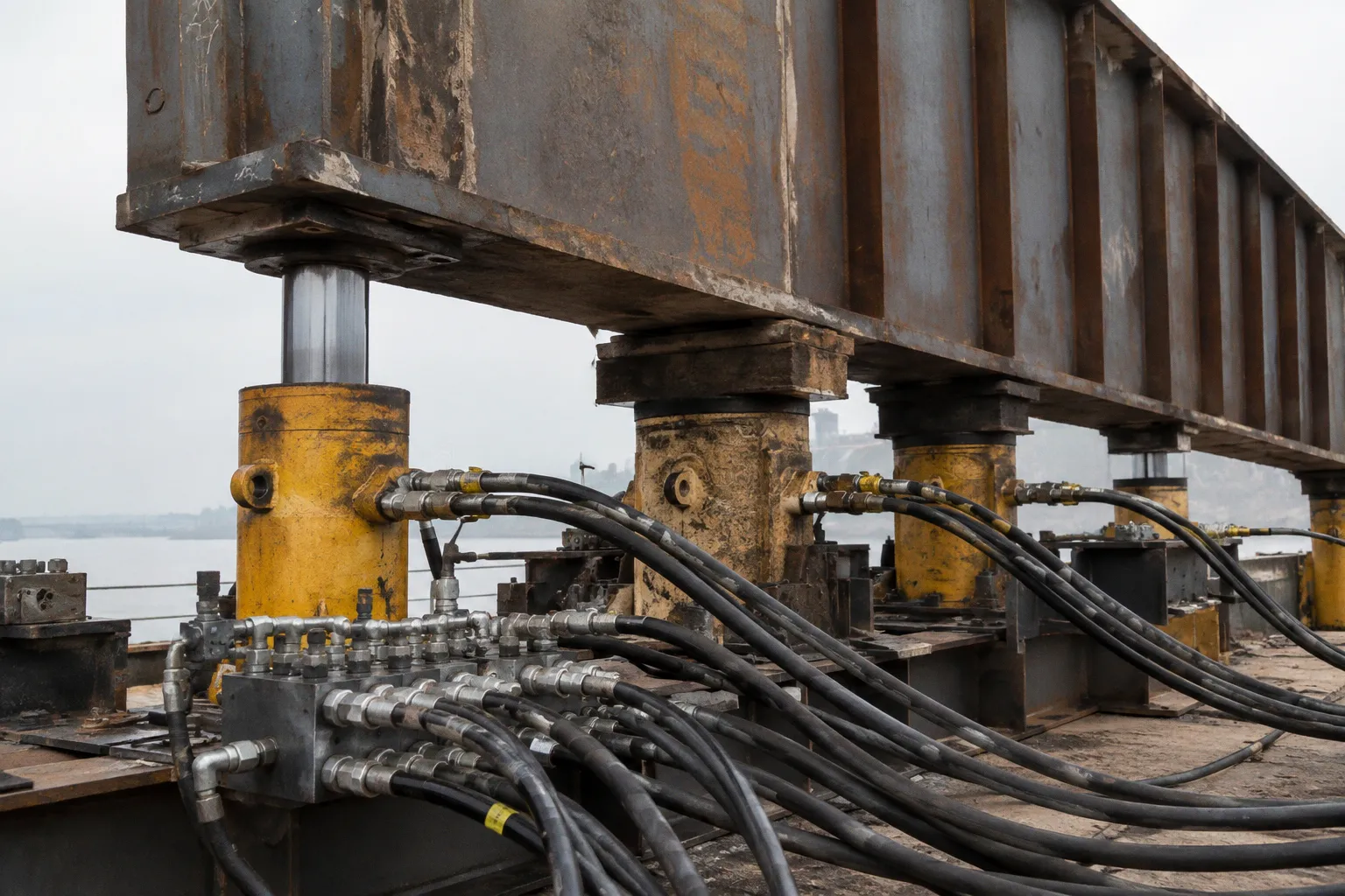
It is a control problem involving load distribution, displacement measurement, hydraulic resistance, structural stiffness, and mechanical restraint.
When a heavy petrochemical module is lifted from multiple points, the principal risk is not only insufficient lifting force. The more common structural problem is differential movement. One cylinder advances faster. One support carries more load. The center of gravity shifts outside the intended lifting geometry. The module twists before the operators can correct it.
This is why synchronous hydraulic lifting load balance depends on feedback rather than pump pressure alone. A reliable system measures what is happening at each lifting point, compares the measurements with the target position, and adjusts oil flow through a controlled hydraulic circuit.
Synchronization is not the absence of movement differences. It is the continuous detection and correction of those differences.
The physics of fluid resistance and load distribution
A hydraulic cylinder converts fluid energy into mechanical force. The pump moves oil into the system. The oil encounters resistance from the cylinder, the lifted mass, friction, piping, valves, and the stiffness of the structure. That resistance produces hydraulic pressure. The pressure acts on the effective piston area and generates lifting force.
The sequence is mechanical, not abstract:
1. The pump supplies oil flow to the hydraulic circuit.
2. The circuit encounters resistance from the load and cylinder movement.
3. Pressure develops in response to that resistance.
4. The pressure acts across the cylinder area.
5. The cylinder produces linear force and displacement.
6. Sensors report the resulting movement and load condition.
7. The controller modifies valve position or flow distribution.
The pump does not create useful pressure in isolation. Pressure becomes meaningful only when the system and load resist fluid movement.
For a single cylinder lifting a centered load, the relationship is comparatively easy to observe. The cylinder extends, the load rises, and the measured pressure corresponds broadly to the required force. A multi-point lifting operation is different. Each lifting point interacts with the same rigid or semi-rigid structure. A change at one point alters the reactions at the others.
A module can therefore display unequal cylinder pressures even when the cylinders are extending at the same nominal speed. The difference may result from:
- An eccentric center of gravity.
- Unequal support stiffness.
- Different cylinder friction.
- Variations in foundation elevation.
- Local deformation in lifting beams or spreader frames.
- Unequal piping resistance.
- Small differences in initial cylinder stroke.
- A structural connection that engages later than expected.
These variables are coupled. A cylinder that carries a higher share of the load may move more slowly. If the control system responds only by forcing that cylinder to extend faster, it can increase the imbalance rather than remove it.
The lifting plan must therefore define more than the required tonnage. It must define the lifting geometry, point reactions, expected center of gravity, allowable differential displacement, temporary supports, and the sequence by which the load transfers from the ground to the hydraulic system.
Load balance is a structural condition
The phrase load balance can be misleading. It does not mean that every cylinder must carry exactly the same force. Equal force is not always physically correct. A module with an offset center of gravity may require different reactions at different lifting points.
The practical objective is controlled distribution. Each support must remain within its allowable reaction and stroke range. The structure must remain within its permissible deformation and stress condition. The module must rise with limited angular change.
Displacement is often the primary synchronization variable because it directly describes the geometry of the lift. Pressure and load measurements remain essential, but pressure alone cannot tell the controller whether the module is level. A high-pressure cylinder may be supporting a local peak in reaction. A low-pressure cylinder may be close to losing contact or may simply be positioned over a more compliant part of the support system.
For heavy module synchronous leveling, the control logic must correlate position with load. A displacement error without a load interpretation is incomplete. A pressure alarm without a displacement interpretation is equally incomplete.
Closed-loop feedback: sensors, PLCs, and valve control
A closed-loop hydraulic jacking control system uses measurements from every active lifting point. Stroke or displacement sensors record cylinder extension or relative movement. Pressure transducers record hydraulic conditions. The signals are transmitted to a programmable logic controller, or PLC.
The PLC compares actual values with the lifting program. It then adjusts valve flow and hydraulic pressure to reduce the difference between the target and the measured condition.
This creates a feedback loop:
- The target position is defined.
- Each lifting point reports its actual position.
- The controller identifies deviations.
- Proportional or solenoid valves alter oil flow.
- The cylinders respond.
- New measurements confirm whether the correction was effective.
The loop must operate continuously. A manual correction made after a visible tilt has developed is already late in a high-consequence lift. Structural twist can accumulate before it becomes obvious from the ground.
A properly configured system can maintain synchronization within approximately ±0.5 mm across multiple jacking points. That figure describes control precision under the relevant operating conditions. It does not mean that every field installation will automatically achieve the same result. Sensor installation, calibration, structural flexibility, hydraulic response, PLC settings, and operator discipline all influence the actual performance.
What the stroke sensor contributes
The stroke sensor provides the most direct measurement of cylinder travel. It allows the control system to identify a point that is advancing too quickly or falling behind.
Suppose four hydraulic cylinders are lifting a rigid skid. If one cylinder extends several millimeters more than the others, the system has a geometric problem even if all pressure readings appear acceptable. The module may be rotating around an axis between the lifting points. A stroke sensor identifies this differential before the rotation becomes large enough to create visible instability.
The sensor must measure the relevant movement, not merely an unrelated component. Cylinder stroke can be a useful proxy for vertical displacement, but the relationship may be affected by:
- Flexibility in the lifting frame.
- Slip or compression in temporary supports.
- Deflection of the module base.
- Movement between the cylinder and its bearing surface.
- Nonvertical force components.
- Foundation settlement.
For this reason, sensor readings should be interpreted against the lifting design and, where required, independent level or survey measurements.
What the pressure transducer contributes
Pressure transducers provide information about hydraulic resistance and load distribution. They help identify a point that is overloaded, unexpectedly unloaded, or behaving differently from the rest of the system.
Pressure is not a direct substitute for a load cell in every configuration. The force inferred from pressure depends on effective cylinder area and the actual hydraulic conditions. Friction, pressure losses, and valve behavior can affect the relationship. A high pressure reading may indicate a high reaction, but it may also indicate resistance in the circuit or a mechanical obstruction.
The most useful interpretation combines pressure with position:
- High pressure and slow stroke may indicate an overloaded point or increased mechanical resistance.
- Low pressure and fast stroke may indicate insufficient load engagement.
- A growing stroke difference with stable pressure may signal geometric or structural flexibility.
- A sudden pressure change with little displacement may indicate impact, binding, or a support transfer.
- A pressure change that is replicated across all points may reflect a system-wide load event rather than a local fault.
This is the logic of multi point hydraulic synchronization. The controller is not chasing a single number. It is managing a set of coupled mechanical states.
Closed-loop systems versus split-flow pumps
Not every hydraulic lifting arrangement uses active feedback. Some systems distribute oil through a split-flow pump or a similar equal-flow arrangement. The principle is straightforward: the pump attempts to deliver comparable flow to multiple cylinders.
This can be effective when the loads are reasonably balanced and the cylinders operate under similar conditions. Split-flow systems can achieve approximately 4% accuracy between cylinders in balanced-load applications. That level of control may be adequate for certain operations with limited differential movement and a predictable structure.
The limitation is fundamental. Equal oil flow does not guarantee equal displacement when the cylinders experience different loads or resistance. A heavily loaded cylinder may extend more slowly than a lightly loaded cylinder receiving the same nominal flow. A split-flow pump does not automatically measure and correct each cylinder’s actual position or pressure.
| Parameter | Split-flow hydraulic system | Closed-loop synchronous system |
|---|---|---|
| Primary control principle | Distributes approximately equal oil flow | Measures each point and corrects the deviation |
| Typical balance capability | Approximately 4% between cylinders under balanced loads | Synchronization can reach about ±0.5 mm error across multiple points |
| Response to unequal loads | Limited without additional feedback | Continuously adjusts flow and pressure according to sensor data |
| Sensor dependency | May operate with limited measurement | Requires displacement and pressure feedback |
| Suitability | Relatively balanced lifting configurations | Heavy, eccentric, flexible, or tightly controlled lifts |
| Main risk | Unequal resistance produces unequal movement | Sensor, calibration, or control failure can compromise correction |
| Control architecture | Simpler | More complex, with PLC and controlled valves |
The distinction is not that one technology is universally safe and the other is universally unsafe. The question is whether the control method matches the load behavior.
A balanced steel frame supported at geometrically similar points may tolerate a simpler hydraulic arrangement. A large petrochemical module with an offset center of gravity, multiple lifting beams, and limited tolerance for twist requires a system that can observe and correct local deviations.
The design should also account for dynamic behavior. A system that responds too slowly allows error to accumulate. A system that responds too aggressively can produce oscillation, pressure surges, or repeated valve corrections. The PLC program must be tuned to the hydraulic response and the stiffness of the lifted structure. Proprietary tuning equations vary by manufacturer and installation. The general principle remains consistent: correction must be proportional to the measured deviation without introducing unstable movement.
Equal flow is a hydraulic intention. Equal displacement is a measured structural result.
Mechanical safety: holding the load after correction
Control software cannot be the only barrier against downward movement. A hydraulic cylinder may maintain position during normal operation, but the lifted load requires a physical holding strategy that remains effective if hydraulic power is lost, a hose fails, or a valve malfunctions.
A robust holding system combines hydraulic and mechanical functions. Hydraulic check valves restrict unintended fluid backflow. Mechanical self-locking mechanisms physically sustain the load. The hydraulic circuit controls the movement; the mechanical system provides restraint.
This division matters because hydraulic pressure is not a permanent support condition. It depends on fluid containment, valve integrity, hose condition, pump behavior, and the absence of leakage. Mechanical locking reduces dependence on continuous hydraulic pressure.
The holding arrangement must be integrated into the lifting sequence. A load is not secure merely because all cylinders have stopped moving. The procedure should define:
- When temporary supports are installed.
- How the load is transferred onto those supports.
- How much movement is permitted during transfer.
- How the hydraulic system confirms that the transfer is complete.
- How the mechanical locks are inspected.
- How the system is re-pressurized before the next lifting stage.
- How emergency lowering or controlled stop conditions are handled.
A stop command also requires interpretation. If one point stops because of a sensor fault while the other cylinders continue, the resulting condition differs from a controlled system-wide hold. The PLC should define the response to sensor disagreement, communication loss, pressure excursions, and stroke limits.
The operator interface must make those conditions visible. A single green status indicator is inadequate for a multi-point lift. The control display should distinguish position, pressure, valve status, alarm state, and lock condition for each point.
Mechanical self-locking is not a software setting
A software command can stop flow. It cannot replace a load path. Mechanical self-locking devices, cribbing, locking collars, or other engineered restraints must carry the load according to the approved lifting method.
The exact arrangement depends on the equipment and project design. The principle is stable: once the module reaches a safe intermediate or final elevation, the load must be transferred into a physical support system before personnel treat the position as secure.
This is especially relevant during installation and alignment. Operators may be tempted to hold a module on cylinders while adjusting anchor points, steel connections, or equipment supports. That creates an extended exposure to hydraulic and structural uncertainty. The safer method is to use engineered temporary supports and define the permissible sequence of adjustment.
Precision during heavy module erection
Sub-millimeter synchronization is useful only when the measurement chain represents the actual structural condition. A displacement sensor can report a precise number while the lifting beam deflects, a support settles, or the module deforms between the sensor location and the critical connection.
Precision therefore has several layers:
1. Sensor precision. The instrument must resolve the required movement.
2. Installation precision. The sensor must be mounted so that its reading corresponds to the intended direction.
3. Calibration precision. Zero position and measurement range must be established before loading.
4. Control precision. The PLC must process the signal and adjust the valves without excessive delay.
5. Hydraulic precision. The valves and cylinders must respond consistently.
6. Structural precision. The lifting arrangement must transmit movement without uncontrolled deformation.
7. Survey precision. Independent measurements must confirm the position of the module.
A weighing system may provide high-precision load measurement with an accuracy of approximately ±0.3%, but that does not eliminate the need for displacement control. Load measurement indicates reaction. It does not, by itself, describe levelness or angular rotation.
The lifting structure also needs a defined reference. If the target is a final equipment elevation, the system must distinguish cylinder stroke from actual equipment position. If the target is a level condition, the system must identify the relevant datum and the acceptable angular tolerance.
A practical lifting sequence
A controlled multi-point lift usually becomes safer when divided into short, observable stages rather than treated as one continuous motion.
1. Establish the initial condition
Record the initial cylinder strokes, pressure readings, support elevations, module level, and expected load distribution. Confirm that every lifting point is engaged as designed. A point that is physically close to the load but not carrying its intended reaction can create a sudden transfer when the lift begins.
2. Apply a controlled pre-load
The cylinders are brought into contact and loaded gradually. This stage reveals unexpected resistance, uneven engagement, and abnormal pressure differences before significant elevation is gained.
The purpose is diagnostic. It is not merely a preliminary movement.
3. Lift in short increments
The controller maintains the target relationship between lifting points. Operators observe the actual response, not only the command value. If a point deviates, the lift should pause or transition according to the approved control logic.
A short increment limits accumulated error. It also provides an opportunity to verify that the module, temporary supports, and lifting frame are behaving as predicted.
4. Reconfirm load distribution
After each defined stage, compare displacement and pressure data. A point that repeatedly carries a disproportionate reaction may require a design review, not repeated valve adjustments. Persistent imbalance can indicate an incorrect center-of-gravity assumption or an unrecognized structural constraint.
5. Install or engage mechanical supports
Once the module reaches the required intermediate elevation, transfer the load to engineered mechanical restraints. Confirm the transfer through pressure response, support engagement, and survey data.
6. Complete alignment and final positioning
Equipment elevation, orientation, anchor bolt alignment, and support contact should be managed after the main lifting risk has been reduced. Hydraulic cylinders may still be used for fine positioning, but the process should not rely on uncontrolled lateral force or improvised packing.
Where BIM and installation data improve control
BIM construction simulation is useful when it represents the actual lifting sequence rather than only the final geometry. A useful model includes the lifting points, temporary supports, module center of gravity, lifting beams, access constraints, and the order in which supports are removed or engaged.
The model can expose conflicts before equipment reaches the site:
- A cylinder may be positioned where a steel brace blocks access.
- A lifting beam may interfere with pipe racks or temporary platforms.
- A required lock position may be inaccessible after the module rises.
- A support transfer may occur at an elevation where the surrounding steel cannot accept the reaction.
- The planned lifting path may conflict with the final installation envelope.
BIM does not replace engineering calculations or field measurements. It improves sequence visibility. The control system still depends on sensors, calibration, and actual structural behavior.
For steel structures, the same principle applies to installation deviation control. Anchor bolt embedment, base elevation, frame plumbness, and connection tolerances affect how the lifted module will seat. If the supporting steel has accumulated installation deviation, the hydraulic system may be forced to compensate for a geometric problem it was not designed to correct.
The correct response is not to increase hydraulic force until the component fits. It is to identify whether the deviation belongs to the structure, the lifting arrangement, or the equipment interface.
Operating pressure and system boundaries
Hydraulic lifting systems may operate at pressures up to approximately 700 bar, or 70 MPa, depending on the equipment and design. High pressure does not automatically indicate high control quality. It indicates the pressure condition required by the hydraulic circuit and load resistance.
A system operating at lower pressure may be correctly matched to its cylinder area and load. A system at high pressure may still have poor synchronization if the control architecture cannot manage unequal reactions.
Pressure limits must be treated as system boundaries. The cylinders, hoses, fittings, manifolds, valves, gauges, and mechanical supports must be compatible with the intended operating range. The weakest component defines the practical boundary, not the nominal capability of the pump.
Pressure alarms should also distinguish between:
- A gradual increase caused by normal load transfer.
- A local spike caused by obstruction or binding.
- A broad increase caused by a support engagement.
- A sudden drop caused by leakage, disengagement, or sensor error.
- A mismatch between measured pressure and expected displacement.
The operator should not respond to every alarm by increasing flow. That can convert a diagnostic signal into a structural event.
A structural verification sequence before the lift
The most useful final control is not a slogan about safety. It is a sequence that links the design assumptions to observable field conditions.
1. Confirm the lifting geometry. Check the position, elevation, orientation, and rated condition of every cylinder, lifting beam, spreader, pin, and temporary support.
2. Confirm the expected reactions. Use the approved load distribution and center-of-gravity assumptions. Do not treat equal cylinder load as the default unless the structure actually requires it.
3. Check the measurement chain. Verify stroke sensors, pressure transducers, signal transmission, PLC inputs, valve outputs, zero settings, and alarm limits.
4. Test the holding system. Confirm hydraulic check valves and mechanical self-locking devices. A stop command is not a substitute for physical restraint.
5. Perform a controlled pre-load. Look for unequal engagement, abnormal pressure, delayed movement, leakage, and unexpected structural contact.
6. Define the stop conditions. Establish the maximum permitted displacement difference, pressure deviation, angular change, sensor disagreement, and communication failure response.
7. Lift in controlled stages. Record the data at each stage. Compare actual displacement and reaction behavior with the lifting plan.
8. Verify the final support transfer. Confirm that the module is carried by the intended permanent or temporary supports before releasing the hydraulic system.
Synchronous hydraulic lifting load balance is therefore a combination of fluid mechanics, instrumentation, control engineering, and structural behavior. The PLC is essential, but it is only one part of the system. Sensors cannot correct an incorrect lifting geometry. A precise controller cannot compensate indefinitely for an underestimated center of gravity. Mechanical locks cannot rescue a sequence that transfers load without confirmation.
The reliable method is direct: measure every critical point, control the differential movement, interpret pressure together with displacement, and secure the load mechanically at each stable stage. That is how multi-point lifting becomes a controlled structural operation rather than a collection of cylinders moving at roughly the same time.