Grout Pad Thickness: Precision Leveling for Heavy Baseplates
A heavy machine does not become precise simply because it has been lifted into position.
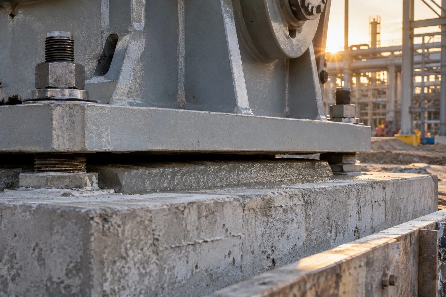
The final accuracy is settled lower down — at the quiet interface between the steel baseplate, the foundation, the shim pack, and the grout pad that must carry the load without losing alignment.
For petrochemical equipment, where rotating machinery, vessels, pumps, compressors, and packaged units are often installed within narrow elevation and centerline tolerances, grout pad thickness for heavy equipment baseplates is not a finishing detail. It is part of the leveling system. The pad must be thick enough to transfer load uniformly, thin enough to remain stable during placement, and compatible with the grout material, flow distance, baseplate geometry, and dynamic behavior of the machine.
The numbers are familiar — 25 mm, 50 mm, 13 mm — but they do not function as universal answers. They are points within a sequence. The foundation surface, the baseplate, the shims, the formwork, the grout flow path, and the final equipment alignment all have to settle into one controlled installation.
What grout thickness is actually doing beneath the baseplate
A grout pad performs several tasks at once.
It fills the irregular space between the prepared concrete pedestal and the underside of the steel baseplate. It distributes the bearing pressure across the support area. It locks the baseplate into its final elevation after temporary shims or leveling screws have established the position. It also helps damp vibration and protects the contact zone from becoming a collection of small, uneven bearing points.
Without a continuous and properly formed grout layer, the baseplate may rest on isolated shims, high spots, or areas of incomplete contact. Under static load, that can create local stress concentrations. Under dynamic load, the same discontinuity can become movement, fretting, vibration, or a gradual loss of alignment.
This is why a baseplate leveling and grouting procedure should be treated as a controlled installation stage rather than as a cavity-filling operation. The pad has a designed thickness, a material-specific behavior, and a geometry that must remain stable while the grout flows and cures.
API 686 practice commonly places epoxy grout thickness beneath machinery baseplates in the range of 25 to 50 mm. ACI 351.1R-99 gives a preferred minimum thickness of 25 mm for hydraulic cementitious grout beneath baseplates. Epoxy grout may have a minimum thickness of 13 mm beneath the baseplate, but that lower limit does not turn every thin gap into a suitable epoxy application. The formulation, bearing condition, flow distance, temperature, and manufacturer’s installation requirements still govern the final choice.
Grout thickness is not the distance left over after leveling. It is the controlled depth of the load-transfer interface.
The distinction matters on large industrial foundations. A wide baseplate can create long flow paths. A deep but poorly confined pour can behave differently from a compact pad. A dynamic machine can demand a more deliberate approach than a static support. The same nominal thickness may be adequate in one arrangement and unsuitable in another.
API 686 and ACI 351.1R-99: related guidance, different material logic
The two standards are often mentioned together because both address machinery grouting and the conditions required for a stable interface. They should not, however, be read as if epoxy grout and cementitious grout were interchangeable materials with one shared thickness rule.
API 686 identifies a commonly used epoxy grout range of 25 to 50 mm under machinery baseplates. That range gives the installer enough depth for placement and load transfer while avoiding an unnecessarily deep resin section. For epoxy grout, the minimum thickness beneath the baseplate may be 13 mm, and the maximum thickness per lift is 457 mm. The lower limit and the per-lift limit describe different installation concerns: one protects against an excessively thin layer, while the other controls the behavior of a deeper pour.
ACI 351.1R-99 treats hydraulic cementitious grout separately. Its preferred minimum thickness beneath a baseplate is 25 mm. Cementitious grout may require a different flow arrangement, different preparation, and different attention to shrinkage and curing. A cementitious non-shrink grout should not be assigned the same minimum and maximum limits as an epoxy resin grout simply because both are called grout.
| Installation parameter | Epoxy grout | Hydraulic cementitious grout |
|---|---|---|
| Common minimum beneath baseplate | 13 mm minimum in the stated guidance; 25–50 mm is a common API 686 range for machinery applications | 25 mm preferred minimum under ACI 351.1R-99 |
| Typical control concern | Resin flow, heat development, confinement, bond, and pour depth | Water demand, curing, flow, restraint, shrinkage control, and surface condition |
| Deep placement | Do not exceed 457 mm per lift under the stated epoxy guidance | Thickness must follow the selected product, project specification, and placement method |
| Foundation surface profile | Must support the specified bond and cleanliness requirements | Roughened to ICRI CSP 6–9 before cementitious grouting |
| Formwork relationship | Forms at the foundation edge and no farther than 152 mm from the baseplate perimeter under API 686 guidance | Geometry and leakage control follow the grout system and approved installation method |
The table is a starting map, not a substitute for the project specification. In an EPC installation, the approved equipment vendor documents, grout manufacturer’s data, foundation drawings, and method statement need to settle into the same sequence before the pour begins.
A practical selection process usually moves through five questions:
1. What is the grout chemistry?
Epoxy and cementitious products have different thickness limits, bonding behavior, curing requirements, and sensitivity to temperature and moisture.
2. What is the required equipment elevation?
The designed grout depth has to coexist with the baseplate elevation, shim pack, anchor bolt projection, leveling screws, and any soleplate or embedded plate arrangement.
3. How far must the grout travel?
A short, open pour behaves differently from a long flow beneath a broad baseplate. Flow length can require additional thickness.
4. What load will the pad carry?
Static vessel supports, rotating machinery, and systems exposed to thermal or cyclic movement do not impose the same demands.
5. How will the pad be confined and inspected?
Formwork, venting, access for placement, and confirmation of full contact are part of the design, not afterthoughts.
Flow length changes the thickness calculation
Large baseplates are where a simple thickness assumption begins to soften at the edges.
When grout must travel a significant distance beneath a plate, resistance to flow increases, and the likelihood of incomplete filling becomes more difficult to control. ACI 351.1R-99 recommends increasing the cementitious grout thickness by 13 mm for each additional 300 mm of flow length beyond the initial 300 mm, up to a maximum thickness of 100 mm.
That relationship is not an invitation to enlarge every pad. It is a way of recognizing that the path beneath the baseplate has geometry. A long flow distance may need more space for the grout to reach the far edge and to maintain a continuous bearing layer. The final arrangement still has to be checked against the selected grout product, the equipment design, the formwork, and the actual placement method.
For example, if the grout must move from one pouring edge beneath a wide baseplate, the far side should not be treated as an invisible region that will fill itself. The installation plan needs a defined flow direction, a means of confirming progress, and a way to prevent trapped air or an isolated dry pocket. On a complex steel skid, multiple pour points may be more reliable than asking one stream to travel across the full underside.
This is also where baseplate geometry and shim pack installation meet. Shims establish the temporary elevation, but they also divide the underside into spaces that the grout must surround. If the shim arrangement blocks flow, sits too close to the pouring edge, or creates unplanned pockets, the nominal pad thickness will no longer describe the actual contact condition.
The desired outcome is not merely a measured depth at the accessible edge. It is a continuous, supported interface below the working surfaces of the baseplate.
Baseplate leveling before the grout arrives
Leveling should be completed with enough patience that the final grout pour does not become a rescue operation.
The foundation elevation is surveyed first against the equipment datum. The baseplate is then brought into position using the specified leveling screws, shims, or a combination of both. Anchor bolts should remain capable of receiving the final tightening sequence without pulling the baseplate away from its established position. Equipment centerlines, shaft elevations, nozzle orientation, and critical clearances are checked before the grout is mixed.
A shim pack is not simply a stack of steel pieces placed wherever a gap appears. It needs to provide stable bearing during leveling and remain compatible with the final grout arrangement. Thin, scattered contact points can allow the plate to flex or settle before the grout has developed strength. A better-controlled arrangement follows the baseplate design and the equipment supplier’s instructions, with the supports positioned so that alignment can be maintained until the grout has cured.
The sequence generally settles through these stages:
1. Survey the foundation and confirm the pedestal elevation against the equipment datum.
2. Clean and prepare the concrete surface, removing laitance, weak material, oil, dust, and loose particles.
3. Install and position the baseplate, leveling screws, and shim packs in accordance with the approved drawing.
4. Establish elevation, level, centerline, and orientation before final tightening.
5. Confirm the available grout thickness at the intended pour locations, not only at one convenient point.
6. Install tight, stable formwork with a controlled flow path and adequate access.
7. Place the approved grout continuously enough to avoid cold joints or trapped voids.
8. Allow curing, then complete the specified release, trimming, inspection, and anchor-bolt sequence.
The precise order can vary by equipment and grout system. What should not vary is the discipline of resolving geometry before material enters the form.
Surface preparation: the foundation must be able to receive the load
A grout pad can only transfer load as well as the concrete beneath it allows. A smooth, dusty, or contaminated surface creates a weak boundary, even when the grout itself has excellent compressive strength.
For cementitious grout, the stated preparation guidance calls for roughening the concrete to an ICRI Concrete Surface Profile of CSP 6 to CSP 9. This is a substantial mechanical profile, not a light sweep with a wire brush. The purpose is to remove weak surface material and create a texture that allows the grout to form a reliable mechanical and adhesive interface.
The surface should be free of laitance, curing compounds, oil, standing water where the product does not permit it, loose aggregate, and debris. The preparation method may include scabbling, abrasive blasting, or another approved mechanical process, but the finished condition has to match the grout manufacturer’s requirements and the project method statement.
At the same time, roughness should not be confused with uncontrolled damage. Deep fractured areas, exposed reinforcement, honeycombing, or weak concrete need their own repair decision before grouting. A rough profile cannot stabilize a deteriorated pedestal.
For epoxy systems, the surface condition also has to be compatible with the resin system and the specified moisture limits. The foundation may need to be dry, clean, and within a defined temperature range. The installer should not assume that a preparation method suitable for cementitious grout automatically suits epoxy grout.
Formwork geometry is part of the pad design
Formwork determines where the grout is allowed to go, how far it must travel, and whether the finished edge remains properly supported.
Under API 686 execution guidance, epoxy grout formwork is placed at the edge of the foundation and should be no farther than 152 mm from the baseplate perimeter. That short distance helps reduce unsupported overhang and keeps the grout close to the load-bearing footprint. A form set too far away may create a wide, thin projection that contributes little structurally but introduces another edge to protect and inspect.
Forms need to be rigid, sealed against leakage, and arranged so the grout can be placed without disturbing the baseplate. Sharp changes in direction, inaccessible pockets, and high points that trap air should be resolved before mixing. On a large petrochemical foundation, the formwork plan may deserve the same drawing-level attention as the steel support itself.
A useful review looks at:
- the distance from each form to the baseplate edge;
- the lowest and highest available grout thickness;
- the direction and length of flow;
- access for pouring, pumping, rodding, or venting as permitted by the product;
- the location of shim packs and leveling screws;
- anchor bolt sleeves and other obstructions;
- the possibility of air entrapment beneath closed or boxed sections;
- the curing and inspection access after placement.
The pad should settle into the form without being forced into a geometry that the design never intended.
A clean foundation and a close formwork line do more for grout reliability than an extra bag of material poured into an uncertain gap.
Compressive strength is only one part of structural integrity
A strong grout is not automatically a suitable grout. Its compressive strength has to relate to the concrete support beneath it, and the complete interface has to remain stable under the actual service condition.
AISC Design Guide 1 recommends that the compressive strength of the grout pad be at least twice the compressive strength of the supporting concrete footing or pedestal. This ratio gives the grout a stronger bearing layer than the concrete beneath it, but it does not remove the need to review bearing pressure, load distribution, edge conditions, anchor forces, vibration, and thermal movement.
The strength relationship should therefore be read together with the geometry. A very strong material placed in a discontinuous or poorly bonded layer does not create uniform support. Likewise, a pad with appropriate nominal thickness can still fail to perform if shrinkage leaves voids, if the concrete surface is weak, or if the baseplate shifts before the grout develops its required properties.
Grout shrinkage control in petrochemical foundations becomes especially relevant where the baseplate supports rotating equipment or where a small loss of contact can alter alignment. Non-shrink cementitious products are formulated for this purpose, but non-shrink does not mean that every field condition is automatically controlled. Water addition, mixing time, placement temperature, curing, and restraint all influence the result.
Epoxy grout brings a different set of concerns. It can provide strong adhesion and useful dynamic performance, but it remains sensitive to the selected formulation, temperature, batch control, and pour depth. Deep epoxy sections may develop heat during curing, which is one reason the per-lift limitation matters. A 457 mm maximum per lift is not a recommendation to create a deep resin block beneath ordinary machinery; it is a boundary within the stated guidance for applications where such depth is being considered.
The installation team should be able to identify the product, batch, mixing procedure, working time, placement temperature, cure requirements, and acceptance criteria before the pour begins. If the material has to be improvised on site because the access, flow path, or gap differs from the approved method, the correct response is to stop and resolve the discrepancy rather than asking the grout to absorb the uncertainty.
The final alignment belongs to the whole installation sequence
Grout pad thickness is often discussed as a single number, but the successful pad is the result of several numbers agreeing with one another.
The foundation elevation determines how much space remains. The baseplate establishes the working plane. The shim pack holds that plane during installation. The flow distance influences the required depth. The grout formulation sets its own lower and upper limits. The formwork controls the perimeter. The concrete strength provides the supporting base. The machine’s operating behavior determines how unforgiving the interface will be.
When these elements are reviewed together, the installation becomes quieter and more predictable. When they are considered separately, the field team can arrive at a pad that is thick enough in one location, too thin in another, difficult to fill, or unsupported at its edges.
For heavy equipment baseplates, a sound starting point is therefore not a memorized thickness but a defined installation envelope:
- epoxy machinery grout commonly falls within a 25–50 mm range under API 686 practice;
- epoxy may require at least 13 mm beneath the baseplate and should not exceed 457 mm per lift under the stated guidance;
- hydraulic cementitious grout has a preferred minimum of 25 mm under ACI 351.1R-99;
- cementitious grout flow lengths beyond 300 mm may call for 13 mm of additional thickness per added 300 mm, up to 100 mm;
- cementitious grout substrates should be prepared to an ICRI CSP 6–9 profile;
- epoxy grout forms should remain within 152 mm of the baseplate perimeter under API 686 guidance;
- grout compressive strength should be considered in relation to the concrete support, with AISC Design Guide 1 recommending at least twice the supporting concrete strength.
These values help the team settle into a controlled decision. They do not replace the equipment vendor’s requirements, the grout manufacturer’s data, the structural design, or the approved project method statement.
The best grout pad is rarely dramatic. It does not announce itself after commissioning. It simply keeps the baseplate supported, the shaft aligned, the vibration contained, and the load moving into the foundation as intended. That quiet performance begins before the mixer starts — with the surface prepared, the elevation understood, the flow path opened, and the thickness chosen for the actual machine rather than for a convenient rule of thumb.