Spring Hangers for Radiant Coils: Managing Thermal Growth
Outer tube wall temperatures in ethylene cracking furnaces can reach 950°C to 1100°C during normal operation. At those temperatures, a radiant coil assembly does not simply become hotter and longer.
It moves—primarily downward and vertically, but also through the connected geometry of risers, return bends, manifolds, and outlet piping.
The movement may be measured in centimetres. It is repeated through heat-up, operation, decoking, cool-down, and restart. If the support system cannot absorb that displacement without feeding a changing load back into the coil, the thermal expansion appears as mechanical stress at the least forgiving points: tube bends, weld toes, branch connections, and tube-to-header joints.
This is the engineering problem addressed by radiant coil constant spring supports. A properly selected constant support maintains an approximately steady supporting force as the coil travels through its operating range. The objective is not to stop movement. It is to let the equipment move without turning the hanger into an unintended restraint.
For vertical thermal displacement above roughly 19 mm, engineering guidance for pipe-hanger selection commonly favours constant spring supports over variable spring hangers. The 19 mm value is a practical design threshold, not a universal code command. Below it, a variable spring may provide acceptable load variation if it is correctly selected. Above it, the change in spring force can become large enough to affect the stress distribution in the coil and the loads transmitted to connected equipment.
The purpose of a constant spring hanger is not to hold a hot coil still. It is to let the coil move while keeping the support load predictable.
The Mechanics of Constant Load Support in High-Temperature Furnaces
A constant spring support is more than a spring enclosed in a frame. It is a counterbalance mechanism designed to maintain a nearly constant output load while the supported pipe changes elevation.
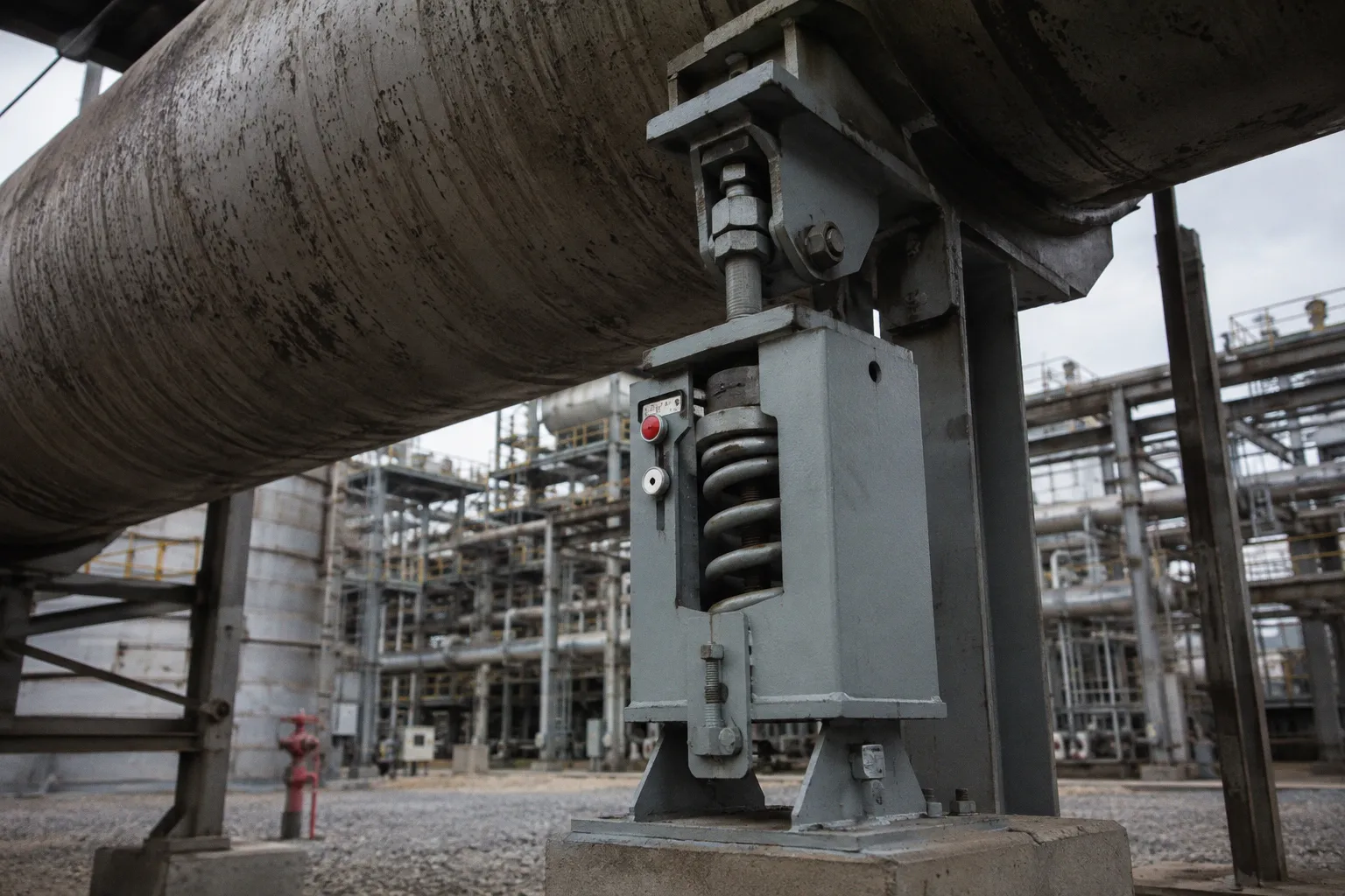
The main elements are a helical spring, a lever or cam arrangement, a load connection, and a frame that controls the geometry. As the pipe moves vertically, the spring compresses or extends. That changes the spring force. At the same time, the lever arm or cam changes the effective moment arm through which the force acts. The mechanism is proportioned so that the increase in spring force is offset by the change in geometry.
In simplified terms, the support is trying to keep the product of force and effective distance nearly constant over the specified travel. The result is a support that can follow the thermal movement of a coil without producing the same load variation that would be expected from a simple spring.
A variable spring hanger behaves differently. Its supporting force changes with compression or extension, normally in relation to the spring rate. The pipe may move exactly as required, but the force at the support changes with that movement. In a lightly loaded or low-displacement application, that change may be acceptable. In a radiant coil system, especially one exposed to repeated furnace cycles, it can become a significant part of the piping stress picture.
The distinction matters at several locations simultaneously:
- the radiant tubes themselves;
- vertical risers and return legs;
- outlet and inlet manifolds;
- transfer lines connected to the furnace;
- pigtails, quench exchangers, or other equipment that receives the coil load;
- structural steel supporting the hanger assemblies.
A constant support does not eliminate all load variation. Practical mechanisms have manufacturing tolerances, bearing friction, spring tolerances, and geometric limits. The commonly specified maximum deviation of approximately 6% describes the allowable variation in supporting force over the rated travel range. It is a design and performance tolerance for the selected support, not a promise that the same force will be reproduced indefinitely through every thermal cycle for the entire life of the furnace.
That distinction should remain visible in the engineering documentation. The 6% value belongs in the load model and equipment selection records. It should not be presented as a universal lifetime guarantee, particularly when the hanger is exposed to heat, contamination, overtravel, incorrect loading, or damage during testing.
| Parameter | Variable Spring Hanger | Constant Spring Support |
|---|---|---|
| Load behaviour over travel | Supporting force changes with displacement | Supporting force remains approximately constant within the specified tolerance |
| Typical application | Smaller thermal movements and systems able to accept load variation | Larger thermal movements and systems sensitive to changing support loads |
| Common selection threshold | Often considered for movement below about 19 mm | Commonly considered when movement exceeds about 19 mm |
| Travel range | Depends on frame and spring selection | Available in a range of travel classes, commonly extending from short movements to several hundred millimetres |
| Field adjustment | Depends on design and manufacturer | Usually limited to fine adjustment around the calibrated load |
| Main engineering concern | Variable force transmitted into the piping system | Correct calibration, alignment, travel, and protection during testing |
The table is a selection aid, not a substitute for a pipe-support calculation. The correct choice still depends on the actual cold and hot loads, the direction of movement, the available travel, the position of neighbouring restraints, and the sensitivity of connected equipment.
When to Transition from Variable to Constant Spring Hangers
The decision should be made from the calculated thermal displacement and load variation, not from the appearance of the hanger or from a general preference for one support type.
For many pipe-support applications, approximately 19 mm of vertical movement is used as a practical boundary in engineering guidance. A variable spring may be suitable below that level when the resulting load change remains acceptable for the pipe, equipment nozzles, and support steel. Once the movement becomes larger, a constant support is often the more controlled solution because it reduces the change in load as the pipe travels.
MSS pipe-hanger and support guidance is relevant to this selection process. It helps engineers choose and apply support types; it does not turn every installation above a particular movement into an automatic code requirement. ASME B31.3 provides the process-piping framework for chemical and refinery service, but it should not be described as mandating constant spring supports whenever connected-equipment loads must be tightly controlled. That conclusion belongs to the engineering evaluation of the piping system and the applicable support guidance.
In ethylene cracking furnaces, radiant coils frequently present the conditions that make the constant-support option attractive. The tube wall operates at a much higher temperature than the surrounding furnace casing and much of the support steel. The coil expands relative to those cooler structures, and the displacement is distributed through a geometry that may include long vertical sections, multiple passes, and closely spaced bends.
The selection becomes especially important when:
1. Connected equipment has narrow load limits.
A coil may be able to tolerate a certain support-load change while a transfer line, exchanger nozzle, or pigtail connection cannot. The support decision must therefore consider the entire load path, not only the hanger attachment point.
2. The coil has a complex multi-pass arrangement.
Adjacent passes may not expand by exactly the same amount. Differences in routing, temperature, restraint, or local stiffness can shift load from one support to another. A variable spring can amplify that redistribution as its own force changes with travel.
3. The furnace operates through severe decoking cycles.
A support arrangement that appears acceptable during steady production may experience a very different load history during controlled heating, coke burn-off, cooling, and restart. The support has to accommodate the full operating sequence, not merely the normal production temperature.
4. The support point is close to a stress-sensitive connection.
A change in support force can become a bending moment at a weld, header, branch, or tube bend. The closer the support is to such a feature, the less useful it is to treat the hanger as an isolated component.
5. The movement is close to the end of the selected travel range.
A nominally correct hanger can still be a poor choice if the hot position leaves no practical margin for installation tolerance, thermal-model uncertainty, or movement beyond the design case.
The thermal displacement should be calculated from the actual coil geometry and temperature assumptions. It should not be estimated from tube length alone. Local temperatures, restraints, friction, guide clearances, and the relative movement of connected components can all change the position that the hanger must accommodate.
Managing Cyclic Thermal Stress in Ethylene Cracking Operations
Ethylene cracking furnaces do not remain at one mechanical condition. The radiant coil moves through a sequence of distinct states: maintenance condition, start-up, heat-up, normal operation, decoking, cool-down, and the next restart. Each transition changes the relationship between the coil, its supports, and the surrounding furnace structure.
The support system therefore sees more than one load event. During heat-up, the coil begins to move while the support steel and adjacent equipment remain at different temperatures. During operation, the hanger must hold the calculated hot load while allowing the coil to settle into its operating position. During decoking, temperature gradients and rates of change can differ from the normal production case. During cool-down, the direction of movement reverses.
The 6% load-deviation figure should be read in that context. It describes how closely the support maintains its rated load across the specified travel range under the applicable design conditions. It is not a statement that the hanger will automatically preserve that performance through every future cycle regardless of maintenance, heat exposure, corrosion, lubrication condition, or mechanical abuse.
The hardware has to retain its geometry for the tolerance to remain meaningful. The relevant components include:
- the helical spring and its seating surfaces;
- the lever, cam, or arm that produces the constant-load effect;
- pivot pins and bearings;
- the load rod and connection hardware;
- the frame and travel guides;
- locking pins and travel stops;
- the position indicator and its reference marks.
Furnace service makes these details less forgiving. Radiant heat can raise the temperature around the support steel well above ambient. Dust, scale, insulation debris, and process-area contamination can interfere with moving parts. A support that is theoretically constant-load may not behave as designed if its pivot binds or if its frame is distorted.
Common design provisions include sealed or high-temperature bearing arrangements, protected moving parts, factory-calibrated spring assemblies, and a limited field-adjustment mechanism. The adjustment range is normally intended to accommodate small differences between the calculated and as-installed load. These differences may come from insulation weight, support hardware, pipe fittings, or minor changes in the final routing.
A field adjustment bolt is not a substitute for correct selection. If the actual load or movement falls materially outside the hanger’s rated range, turning the adjustment bolt does not change the basic geometry, spring capacity, or travel capability. A support that needs to be forced beyond its intended adjustment range should be re-evaluated and, where necessary, reselected.
The same applies to alignment. A constant spring support is designed primarily for the intended direction of travel. If the load rod is pulled sideways, the mechanism may receive a lateral component that was not included in the vertical load calculation. The result can be binding, uneven wear, frame loading, or a false indication of the actual vertical support condition.
For that reason, the support arrangement should be reviewed as a system:
- Is the hanger rod aligned with the expected movement?
- Can the coil move through the full hot-to-cold range without striking guides or steelwork?
- Are neighbouring guides and restraints allowing the calculated movement?
- Does the support remain within its rated travel at both ends?
- Are the cold and hot loads consistent with the design model?
- Is the connected equipment receiving the load range assumed in its design?
A constant support can control one part of the problem only if the surrounding support arrangement permits the movement it was selected to accommodate.
Field Calibration and Hydrostatic Testing Protocols
Hydrostatic testing is one of the most important periods in the life of a new coil system because the test condition is not the same as the operating condition.
The coil is designed to carry process fluid, vapour, or gas during operation. During a hydrostatic test, it carries water. The added water weight can substantially increase the dead load on the pipe and its supports. A constant spring hanger calibrated for the dry operating configuration may not have the travel or load capacity required for the filled test condition.
If the supports remain free during testing, the additional weight can drive the mechanism away from its intended position. Depending on the arrangement, the spring may approach its limit, the load rod may move beyond its normal range, or the frame and lever system may be exposed to forces that were not part of the operating design. Damage may not be obvious immediately. A support can appear intact while its calibration, alignment, or moving clearances have already been affected.
During hydrostatic testing, the water load must be treated as a separate support condition. A hanger calibrated for a dry hot coil should not be expected to carry a filled test system without the specified restraint or temporary support arrangement.
The usual procedure is to secure constant spring supports in their installed cold position before filling the system for hydrostatic testing. This may involve the manufacturer’s locking pins, travel stops, or another approved restraint arrangement. The exact method belongs in the project installation procedure and the hanger manufacturer’s instructions.
With the supports locked, the pipe system is held in a defined position while the test load is carried by the structure or by the temporary support arrangement intended for that purpose. After testing, the system should be drained, the test restraints removed, and the hangers returned to their free operating condition before heat-up.
The reason for the procedure is displacement as much as load. It is not enough to compare the test pressure with the hanger’s maximum rated load. Pressure acts on the pipe wall and test boundaries; water weight changes the gravitational load carried by the supports. The concern is whether the support can safely accommodate the resulting position and force without overtravel or damage.
Field calibration begins before the first heat-up. The following records are more useful than a single commissioning sign-off:
1. Record the installed cold position.
Note the travel-indicator position after the pipe, insulation, support hardware, and connected components are in their as-installed condition. This is the baseline for later comparison.
2. Confirm the calibrated load.
Check that the support’s stated load corresponds to the calculated support-point load. The available field adjustment should be used only for fine correction within the manufacturer’s permitted range.
3. Verify free movement.
Remove installation locks as required, confirm that the rod and mechanism can move, and check that the hanger is not restrained by temporary steel, scaffolding, insulation, guides, or adjacent components.
4. Observe the first heat-up.
Compare the actual travel direction and final position with the predicted movement. The indicator should move in the direction established by the thermal model, not merely move by some arbitrary amount.
5. Inspect after the first operating cycle.
Look for contact marks, frame distortion, rod misalignment, damaged indicators, or evidence that the mechanism has reached a travel limit.
6. Repeat the inspection at planned outages.
A return to a position consistent with the cold baseline supports confidence that the mechanism is not binding. A persistent offset calls for investigation rather than automatic adjustment.
Many constant supports permit only a limited angular deviation between the hanger rod and the intended vertical axis. A value such as ±4 degrees may be specified for a particular design, but the applicable manufacturer’s limit should govern. Excessive angular deflection can introduce side loads and may indicate a problem with the support steel, pipe routing, or hanger location.
Interpreting Visual Indicators for Cold and Hot Operating Positions
The visual indicator is a simple but useful link between the support calculation and field observation. It does not replace a load test or a detailed piping analysis. It tells the installer and inspector whether the mechanism is broadly occupying the position expected for the cold or hot condition.
Many constant spring hangers use contrasting reference markers. A white marker or button commonly identifies the installed cold position, while a red marker or button identifies the expected hot operating position. The exact colours and arrangement vary by manufacturer, so the equipment documentation remains the controlling reference.
The marks are factory-set or established from the specified travel for the application. They should be treated as reference points, not as laboratory-grade measuring instruments. Small differences between predicted and observed position can arise from operating temperature, insulation condition, friction elsewhere in the system, or variations between the design and the as-built arrangement.
At ambient conditions, the indicator should be close to the documented cold reference. If it is not, the first questions should concern installation condition, locking devices, rod alignment, and unintended restraint. Adjusting the spring before finding the cause can hide the problem rather than correct it.
During heat-up, the indicator should move in the expected direction. The movement confirms that the coil is transferring its thermal expansion into the intended support path. At operating temperature, the indicator should approach the hot reference established for that hanger.
Several visual patterns deserve immediate attention:
The indicator remains at the cold position during heat-up.
The hanger may still be locked, the mechanism may be seized, or another restraint may be preventing the coil from moving. The support should not be assumed to be healthy simply because it has not travelled. A thermally expanding coil that is prevented from moving must accommodate the expansion through increased stress.
The indicator moves in the wrong direction.
This may point to an incorrect support orientation, a routing change, an error in the thermal model, or movement being redirected through an unintended restraint. Direction is part of the design, not a cosmetic feature of the indicator.
The indicator stops before reaching the expected hot position.
Possible causes include friction, guide interference, insufficient thermal movement, an incorrect operating condition, or a support that is not carrying the load assumed in the calculation. The finding should be compared with neighbouring supports and with actual furnace temperatures.
The indicator moves beyond the hot reference.
The actual displacement may exceed the design value, or the hanger may have been selected with insufficient travel. Higher-than-assumed temperatures, changed insulation, altered routing, or an inaccurate thermal model can all contribute. The support may no longer be operating within its intended travel envelope.
The indicator does not return toward the cold reference after shutdown.
A permanent offset can indicate binding, damage, spring relaxation, frame distortion, or continued restraint elsewhere in the system. It is a condition to investigate before the next heat-up.
A support that has been overloaded during hydrostatic testing, driven into overtravel, or damaged by frame deformation should not be brought back into service merely by turning the adjustment bolt. The adjustment is for installation and load fine-tuning. It does not restore the original geometry of a bent frame, a damaged bearing, or a spring that has lost its intended characteristics.
Bringing the Support Calculation Back to the Furnace
The final review should connect the hanger data to the complete radiant-coil model. A support is correctly selected only when its load, travel, position, and installation condition agree with the system around it.
Before commissioning, the engineering and field teams should be able to answer four practical questions:
1. Is constant support justified by the calculated movement and allowable load variation?
The approximately 19 mm threshold can guide the initial choice, but the final decision must include connected-equipment loads, coil geometry, and the actual thermal case.
2. Does the support cover the complete cold-to-hot travel?
The rated travel must include the calculated displacement with reasonable installation and modelling margin. Operating at the end of the range leaves little room for real-world variation.
3. Does the calibrated load match the as-installed condition?
Pipe weight, insulation, fittings, temporary items, and connected components all contribute to the support load. The field adjustment range is for controlled correction, not for rescuing a mismatched selection.
4. Can the support move without unintended restraint or side loading?
Guides, anchors, structural steel, insulation, access platforms, and temporary test hardware can all interfere with movement. The hanger cannot maintain constant load if the system prevents it from travelling.
The most reliable practice is to treat the cold position, hot position, hydrostatic test condition, and outage condition as separate states and document each one. That approach makes it easier to distinguish a normal thermal movement from a mechanical problem.
Radiant coils are designed to move. The support system should make that movement orderly, predictable, and compatible with the rest of the furnace. Constant spring supports are valuable not because they eliminate thermal growth, but because they prevent that growth from becoming an uncontrolled change in load at the coil and its connected equipment. When the 19 mm selection guidance, the approximately 6% travel-range tolerance, the hydrostatic testing procedure, and the field indicators are treated as parts of one engineering system, the hanger remains what it was meant to be: a controlled path for movement rather than another source of stress.