Fired Heater Air Preheaters: Draft Control and Heat Flow
API Standard 560 specifies that fired heaters in general refinery service operate with approximately 20% excess air at the burner. That figure is not arbitrary.
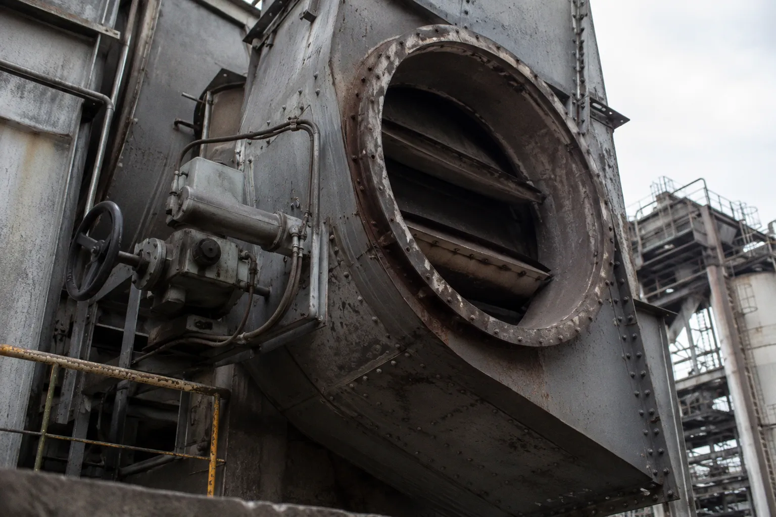
It is the minimum surplus required to ensure complete fuel oxidation across the burner field under variable process load. The combustion air that supplies this surplus enters the firebox at ambient temperature unless it first passes through an air preheater.
A preheater is a heat exchange device positioned between the convection section outlet and the ID fan inlet. It transfers residual thermal energy from the flue gas stream to the incoming combustion air before that air reaches the burner. The result is a measurable reduction in fuel demand and a corresponding lift in adiabatic flame temperature. The transfer also imposes a pressure drop on the draft system — and managing that pressure drop is the function of draft control.
The air preheater does not generate energy. It captures energy that the flue gas would otherwise discharge into the stack.
Thermodynamic Principles of Combustion Air Preheating
Combustion air preheating is a closed-loop convective heat transfer problem. Hot flue gas leaving the convection section of a fired heater carries residual thermal energy. This stream contacts the cold combustion air supply across a heat exchange surface. The temperature lift on the air side is determined by three variables:
1. The log mean temperature difference (LMTD) between the flue gas and air streams
2. The surface area of the heat exchange element
3. The heat capacity rates of the two streams, evaluated at their respective mass flow rates
When the air-side heat capacity rate exceeds the gas-side rate, the air experiences a smaller temperature rise per unit heat exchanged. This is the operating regime of most refinery process heaters, where combustion air demand is fixed by fuel composition and the API 560 excess air specification.
The practical efficiency of the transfer depends on the air outlet temperature at the burner inlet. API 560 design standards describe process furnaces with heating capacities up to 60 MW. Within that envelope, the air preheater is sized to recover a defined fraction of available waste heat at design load. Typical combustion air preheat temperatures at the burner inlet range from approximately 200°C to 350°C, depending on heater size, fuel sulfur content, and the constraints imposed by cold-end corrosion.
The thermodynamic benefit is direct. Preheating the combustion air reduces the fuel required to maintain a given process outlet temperature. The mechanical cost is the pressure drop imposed on the draft system — a cost paid by the ID fan in added work and by the operator in tighter control margins.
Mechanical Configuration of Regenerative and Tubular Exchangers
The heat exchange surface in an industrial air preheater falls into two mechanical categories: regenerative and recuperative.
Regenerative preheaters, most commonly the rotary type, use a slow-rotating matrix that alternately passes through the hot flue gas stream and the cold combustion air stream. As the matrix rotates, it absorbs heat from the flue gas in one sector of the housing, then releases that heat to the incoming air in a separate sector. The matrix is typically a metallic lattice of corrugated plates. Cast iron and ceramic variants exist for high-temperature service and for corrosion-prone applications.
Tubular preheaters, the recuperative type, pass the two streams through separated flow channels divided by tube walls. There is no rotational seal, no mixing zone between hot and cold streams, and minimal cross-leakage. Plate-type exchangers operate on the same principle with stacked plate geometry rather than tubes. Glass tubes and enamel-lined tubes are used in the cold end where acid condensation is a concern.
| Parameter | Rotary Regenerative | Tubular Recuperative |
|---|---|---|
| Heat transfer coefficient | High — large surface area per unit volume | Moderate |
| Cross-leakage between streams | Typically 5–10% of gas volume | Below 1% |
| Cold-end corrosion susceptibility | High — matrix exposed at low temperature | Lower — material selection by zone |
| Capital cost per unit area | Moderate | Higher |
| Maintenance access | Bearing and seal replacement | Tube bundle cleaning or replacement |
The selection between configurations is rarely purely thermal. Rotary units deliver higher heat transfer per unit volume, but cross-leakage between air and gas streams reduces net efficiency and introduces a parasitic draft loss. Tubular units minimize leakage but occupy more plot space and require more frequent cleaning in fouling service.
API 560 addresses both configurations within its general refinery service scope. The standard specifies materials of construction, mechanical design tolerances, and inspection intervals for the assembled air preheater. The standard does not apply to steam reformers or pyrolysis furnaces. Those specialized furnace types are excluded from API 560 scope and governed by separate specifications.
Draft Control Dynamics: Balancing FD and ID Fan Operations
Draft is the pressure differential required to move combustion air into the furnace and exhaust flue gas through the convection section, air preheater, and stack. The system is mechanical: a combination of forced-draft (FD) and induced-draft (ID) fans, motor-driven dampers, ductwork, and the furnace chamber itself.
In a balanced-draft arrangement, the FD fan supplies combustion air at a pressure slightly above atmospheric. The ID fan extracts flue gas at a pressure slightly below atmospheric. The furnace chamber sits between these two references. Furnace pressure is maintained at a slightly negative value, typically within a band of approximately -2 to -10 mm water column relative to ambient, to prevent hot gas leakage into the operating area.
Furnace pressure is not a combustion metric. It is a structural integrity constraint.
The control loop operates as a continuous regulation:
1. A pressure transmitter mounted in the firebox senses absolute furnace pressure at a reference elevation.
2. The transmitter signal feeds a controller, typically a PID loop.
3. The controller modulates the ID fan damper position or the ID fan variable-frequency drive.
4. The FD fan tracks the ID fan to maintain the air-to-fuel ratio specified for stable combustion.
If the ID fan extracts more draft than the FD fan supplies, furnace pressure drops below the control band. Combustion air infiltrates through observation ports, tube penetrations, and shell joints. The flue gas is diluted, flame temperature drops, and process heat release falls. If the FD fan overpowers the ID fan, the furnace goes positive. Hot combustion gases leak outward through the same openings, creating a burn hazard at inspection points and, in extreme cases, structural loading on the furnace shell.
Positive furnace pressure is therefore a safety and integrity constraint, not merely a combustion parameter. The control objective is sustained slight negative pressure across the full operating load range.
Pressure Management and Furnace Integrity Standards
The mechanical specification of a fired heater and its air preheating system is governed by API Standard 560 — Fired Heaters for General Refinery Service. The current revision is the 5th Edition, published in February 2016, with the original standard issued in September 1995.
API 560 defines the design envelope within its scope:
- Design pressure and temperature limits for fired heaters and their air preheaters
- Material specifications for components exposed to combustion products
- Fabrication, examination, and testing requirements
- Draft system sizing methodology, including damper leakage classes
- Inspection intervals and retirement criteria for the assembled unit
Within this framework, draft control is treated as a furnace integrity discipline. The mechanical specification includes damper leakage classes for isolation dampers, fan performance requirements, and the pressure drop budget allocated to the air preheater within the total draft system.
The exclusion clause matters operationally. API 560 does not apply to ethylene cracking steam reformers or pyrolysis furnaces. Those specialized units operate under thermal, mechanical, and process conditions outside the standard's defined scope — radiant section geometries, tube metallurgy, and process residence times that differ substantially from general refinery fired heaters. Specifying API 560 for those services is a category error and should be avoided.
For a heater within API 560 scope, the draft system is sized as a calculation, not a selection. The required total draft pressure at the ID fan is the sum of all pressure drops along the gas path:
P_total = P_burner + P_convection + P_APH + P_stack + P_dampers
Each term is a measurable quantity at design flow. Fans are then specified to deliver this total pressure with margin for control bandwidth, fouling allowance, and altitude correction. A fouled air preheater shifts this calculation by increasing P_APH and forcing the fans to a new operating point.
Mitigating Cold End Corrosion in Heat Recovery Units
The cold end of an air preheater is the section of the heat exchange surface closest to the combustion air inlet — the location where flue gas temperature reaches its minimum before passing to the ID fan and stack. This is also the section where flue gas temperature approaches or drops below the acid dew point of the combustion products.
When the fuel contains sulfur, the flue gas carries SO2 and a small fraction of SO3. At temperatures below approximately 150–180°C — the exact value depends on SO3 concentration and moisture content — sulfuric acid condenses on the metal surfaces. The result is cold end corrosion: progressive metal loss that, in severe cases, penetrates tube walls in tubular units or compromises the structural lattice of a rotary matrix.
Prevention requires controlling several variables simultaneously:
- Maintain flue gas exit temperature above the dew point across the full operating load range
- Specify sulfur content in the fuel supply contract where the operating context allows
- Select cold-end materials for corrosion resistance — glass tubes, enamel-coated elements, or corrosion-resistant alloys in the affected zone
- Use bypass dampers to route a portion of hot flue gas around the cold end during low-load operation
- Schedule periodic soot blowing or wash cycles to remove deposits that retain moisture against the metal surface
API 560 provides guidance on materials selection for these service conditions. The operational discipline — keeping flue gas exit temperature above the dew point at minimum load — is the controlling factor. Material upgrades are a secondary defense.
Operating Envelope: A Concrete Reference Set
The following parameters define the operating envelope of a fired heater air preheater system within API 560 general refinery service:
- Combustion air preheat temperature at burner inlet: typically 200–350°C
- Excess air at the burner: approximately 20% per API 560 specification
- Furnace chamber pressure: slightly negative, approximately -2 to -10 mm water column relative to ambient
- Flue gas exit temperature at the cold end of the preheater: maintained above the acid dew point of the fuel
- Cold-end material: selected for sulfur content of the fuel and minimum flue gas temperature
- Draft pressure drop allocation: P_total calculated as the sum of burner, convection, APH, stack, and damper losses
These are not fixed design values. They are operating bands that respond to fuel composition, process load, ambient conditions, and the mechanical condition of the heat exchange surface. A fouled preheater increases draft pressure drop, shifts the operating point of both fans, and reduces the achievable air preheat temperature. Regular cleaning and inspection restore the design thermal and mechanical performance.
Closing
Fired heater air preheating is a mechanical optimization problem. The thermodynamic benefit — reduced fuel consumption at constant process duty — is real and measurable. The mechanical cost — added pressure drop along the gas path — is equally real. Draft control is the engineering discipline that balances these two quantities across the operating load range, holding the furnace at a slightly negative pressure that protects both process efficiency and structural integrity.
API Standard 560 provides the mechanical framework for that balance within general refinery service. The standard defines materials, draft sizing methodology, and inspection intervals for fired heaters, air preheaters, fans, and dampers. It does not, and explicitly does not, cover the specialized conditions of ethylene steam reformers and PyPyrolysis furnaces. Within its stated scope, however, the standard is the reference document against which the air preheater and its draft system are designed, built, operated, and maintained.