Convection Section Finned Tubes: How Surface Geometry Works
The fired heater convection section is limited less by furnace volume than by the gas-side resistance to heat transfer. Process fluid moves inside the tubes. Flue gas moves across the outside.
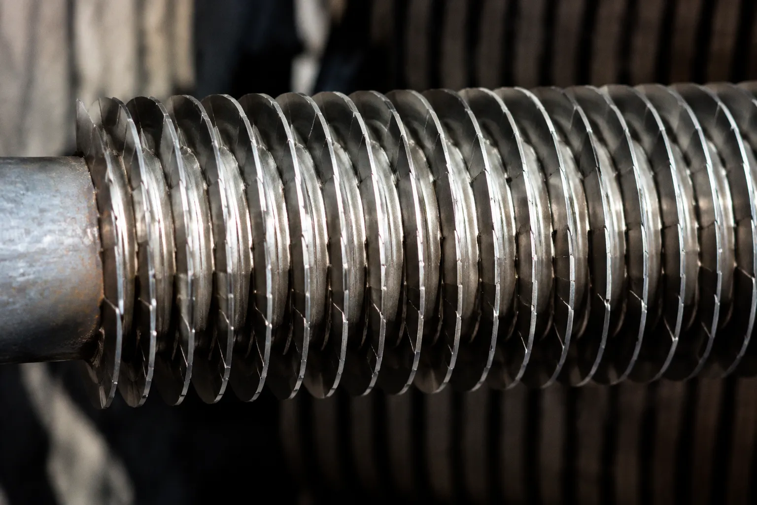
In many heater designs, the external gas film is the weaker thermal link, so increasing tube surface area becomes more effective than simply increasing tube diameter or process-side velocity.
This is the purpose of convection section finned tubes. A finned tube can provide roughly three to ten times the external surface area of a bare tube. That increase is not a cosmetic modification. It changes the available heat-transfer area, the gas-flow field, the pressure drop, the fouling response, and the temperature distribution through the bank.
The correct fin geometry is therefore a thermal and mechanical decision at the same time. A denser or more aggressive fin pattern may improve heat transfer locally while increasing draft resistance or creating a fouling surface that is difficult to clean. In a fired heater, those variables cannot be separated.
The physics of surface area expansion in a convection bank
A convection bank transfers heat from the flue gas to the process fluid through several resistances:
1. Convection from the flue gas to the fin and tube surface.
2. Conduction through the fin metal and tube wall.
3. Convection from the inner tube wall to the process fluid.
The overall heat-transfer rate depends on the combined resistance of these stages. The resistance on the gas side is often dominant because combustion gases have a lower heat-transfer coefficient than a turbulent liquid or gas flowing inside the process tube.
A bare tube exposes only its cylindrical wall to the flue gas. A finned tube adds thin metal surfaces that extend into the gas stream. Heat absorbed by the fins conducts back to the tube wall and then into the process fluid. The tube remains the structural and process-pressure component. The fin is an area multiplier.
The relationship is commonly expressed in the form:
Q = U × A × ΔT
where:
- Q is the heat-transfer duty;
- U is the overall heat-transfer coefficient;
- A is the effective heat-transfer area;
- ΔT is the relevant temperature difference between flue gas and process fluid.
Fins primarily increase A. They can also alter U by disturbing the gas boundary layer, but that benefit is not automatic. The fin must remain thermally active. If the outer portion of a fin becomes too cool or too poorly connected to the tube, its additional area contributes less than the geometric calculation suggests.
Why gas-side resistance matters
A flue gas boundary layer forms as the gas passes over the tube surface. Close to the metal, gas velocity falls and temperature changes rapidly. This layer acts as a thermal barrier. A straight, uninterrupted flow path allows the boundary layer to grow. As it becomes thicker, the local heat-transfer coefficient tends to decline.
Fins affect this process in two ways.
First, they add surface area. Second, they modify the path of the gas through the bank. Depending on their shape, spacing, and height, they create local acceleration, separation, mixing, and reattachment. These effects can thin or repeatedly disrupt the thermal boundary layer.
That is why two tubes with the same nominal outside diameter can produce different convection performance. The fin profile determines how much of the added metal area is useful and how much resistance the bank imposes on the flue-gas path.
Area does not operate in isolation
A common design error is to treat fin density as a direct efficiency control. More fins per metre create more area, but the gas must still pass through the available flow channels. As fin density rises, the open flow area decreases. Pressure drop increases. Draft demand rises. The heater may require more fan capacity or develop a less favorable furnace pressure profile.
The operating consequence is a balance:
- Additional area can increase heat absorption.
- More obstruction can reduce gas throughput.
- Greater turbulence can improve the local heat-transfer coefficient.
- Higher turbulence can also increase pressure loss.
- More metal can create more locations for ash, soot, and particulate deposits.
- A compact bank can become more difficult to inspect and clean.
The optimum convection bank is not the bank with the maximum metal surface. It is the bank that delivers the required duty within the available draft, temperature, fouling, and maintenance limits.
Fins improve a fired heater only when their added area remains thermally active, aerodynamically acceptable, and cleanable under real operating conditions.
Solid versus serrated fin profiles
The two principal fin geometries in fired-heater convection banks are continuous solid fins and serrated, or segmented, fins. Their difference is not limited to manufacturing appearance. They produce different gas-flow patterns and different fouling behavior.
A solid spiral fin forms a continuous helical surface around the tube. It offers a substantial increase in area and creates a defined flow path across the bank. A serrated fin is interrupted into segments. The discontinuities repeatedly disturb the flue-gas boundary layer and promote local mixing.
The comparison is best understood through the interaction between heat transfer and pressure drop.
| Parameter | Solid spiral fin | Serrated or segmented fin |
|---|---|---|
| Surface continuity | Continuous metal path around the tube | Interrupted segments with regular gaps |
| Boundary-layer behavior | More stable flow path; boundary layer can develop along the fin | Repeated disruption, separation, and reattachment |
| Gas-side heat transfer | Effective through increased area; usually less aggressive mixing | Higher local turbulence and generally higher heat-transfer coefficients |
| Pressure-drop tendency | Often lower for a comparable area arrangement | Can be higher because of increased flow disturbance |
| Deposit behavior | Continuous surfaces may retain deposits | Open segments may improve disturbance but can also create deposit pockets |
| Typical design concern | Lower turbulence may limit performance where gas-side resistance is severe | Fouling, cleaning access, and draft capacity require closer control |
| Application logic | Useful where predictable flow resistance and robust construction are priorities | Useful where enhanced convection justifies additional aerodynamic complexity |
What serration actually changes
Serration does not create heat from nowhere. It changes the way the flue gas contacts the surface.
As gas encounters a segmented fin, the flow is interrupted. A small wake forms behind the segment, and the gas mixes with adjacent layers. The next segment encounters a less-developed boundary layer than it would in a continuous path. This repeated disturbance can raise the effective gas-side heat-transfer coefficient.
The result is often better heat transfer than with continuous solid spiral fins at a similar basic geometry. But the increase comes with a cost. The same disruption that improves mixing also consumes pressure head. The convection section must be evaluated as part of the complete flue-gas circuit, including the radiant chamber, bridgewall region, convection bank, air preheater, stack, and draft equipment.
A serrated fin pattern that performs well in a clean design calculation may behave differently after fouling. Deposits reduce the free passage between fins. The effective hydraulic diameter changes. The pressure drop increases. The surface temperature profile may also change because deposits add thermal resistance between the gas and the metal.
Serrated fins are not a universal upgrade
In gas-fired service, serrated fins can be attractive because the fuel typically produces less particulate fouling than heavy oil combustion. Even there, the choice depends on fuel composition, excess air, gas velocity, cleaning provisions, and the required duty.
In heavy oil-fired or combination-fired heaters, soot and particulate deposition become more serious. Studded tubes are often preferred because deposits can be removed more readily with sootblowers or lances. A fine segmented fin pattern may increase the number of narrow spaces where deposits accumulate and may complicate cleaning.
This is the practical limitation behind many fin-selection decisions: the highest clean-condition coefficient is not necessarily the best lifetime coefficient.
Fin density, height, and thickness
Fin geometry is defined by more than the choice between solid and serrated construction. Fin density, height, thickness, and attachment quality all affect the working performance of the convection bank.
Fin density
Fin density describes the number of fins along a unit length of tube. In gas-fired heater guidance associated with API 560 practice, fin density is typically limited to approximately 157 fins per metre, or 4 fins per inch. For fuel-oil or combination-fired heaters, the typical maximum is lower: approximately 118 fins per metre, or 3 fins per inch.
These limits reflect more than fabrication convenience. Higher density reduces the clear gas passage and increases the potential for fouling. Oil-fired service requires greater allowance for soot and particulate deposits, so a more open geometry is generally preferable.
The effect of density is nonlinear in operation. The first increase in fins may add useful area efficiently. Later increases can produce diminishing returns because:
- adjacent fins shield portions of one another from the main gas stream;
- the gas-flow passage becomes more restrictive;
- the fin base remains hotter than the fin tip;
- fouling occupies a larger fraction of the reduced open area;
- cleaning becomes less effective.
A calculation that counts every square millimetre of metal as equally productive can overstate the benefit of a dense bank.
Fin height
Fin height increases the radial reach of the extended surface. The stated standard limit in the supplied design data is approximately 25 mm, or 1 inch.
A taller fin provides more area, but the outer region is farther from the tube and depends more strongly on conduction through the fin metal. The fin temperature falls from the tube base toward the tip. If the fin is too tall, too thin, or exposed to an unfavorable temperature gradient, the tip area contributes less to the total heat transfer.
Fin height also changes the gas-flow channel. High fins occupy more cross-sectional area and can increase turbulence and pressure drop. Their performance must therefore be assessed with the actual tube pitch and bank arrangement, not as an isolated tube property.
Fin thickness
The minimum fin thickness identified in the design data is approximately 1.5 mm, or 0.06 inch. Thickness affects thermal conduction, mechanical durability, corrosion allowance, and resistance to deformation during fabrication and service.
A very thin fin has lower thermal mass and may be more vulnerable to distortion, oxidation, or mechanical damage. A thicker fin conducts heat more effectively toward the outer surface, but it also occupies more flow area and adds weight. The correct thickness is a compromise between thermal activity and long-term integrity.
The attachment between fin and tube is equally important. Poor contact increases thermal contact resistance. The fin may appear continuous while functioning as a series of partially insulated strips. In a high-temperature convection bank, weld quality, attachment geometry, dimensional consistency, and examination requirements have direct thermal consequences.
Geometry must be evaluated as a set
The key variables interact:
- High density with low height produces a compact, restrictive bank.
- Low density with high fins produces fewer but deeper flow obstructions.
- Thin fins increase area with lower metal volume but may lose thermal effectiveness at the tip.
- Thick fins improve conduction and robustness but reduce free passage.
- Serrated profiles increase mixing but can raise pressure drop and deposit sensitivity.
No single parameter defines the quality of a convection bank. The bank must be evaluated as a complete gas-side resistance and maintenance system.
Thermal integrity and material selection
The fin operates in a different thermal environment from the process fluid inside the tube. The tube wall temperature is controlled by the internal process flow, while the fin is exposed directly to hot flue gas. Local temperature can vary substantially along the fin surface and from row to row.
Carbon steel fin metal temperature should not exceed approximately 454 °C, or 850 °F, at the hottest point during normal operation according to the supplied industry specifications. This is a fin-metal limit, not a furnace-gas limit and not a general statement that every component in the heater has the same allowable temperature.
The limit matters because the fin may reach a temperature at which oxidation, loss of mechanical strength, or accelerated degradation becomes unacceptable even if the tube itself remains within its design envelope.
The fin temperature profile
The fin base is usually closer to the tube temperature. The fin tip is influenced more directly by the flue gas. Heat must conduct through the fin from the exposed outer region toward the tube. The temperature profile depends on:
- fin thermal conductivity;
- fin thickness and height;
- gas temperature and velocity;
- tube-wall temperature;
- contact quality at the fin-to-tube attachment;
- deposit thickness;
- local radiation from the firebox;
- neighboring tube and fin geometry.
A deposit layer can produce contradictory effects. It may insulate the fin from the gas and reduce heat transfer. It can also create local hot spots by restricting flow, changing gas distribution, or preventing heat from reaching the process fluid. The deposit is not simply an additional surface. It is a new thermal resistance and a new flow obstruction.
Material selection follows the exposure
Carbon steel fins are common where the calculated fin temperature and corrosion environment allow them. Higher-temperature or more aggressive services may require different tube or fin materials, but material selection cannot be made from the gas temperature alone.
The relevant question is the metal temperature at the actual location of interest. A tube in the upper convection section may experience a different duty from one near the shield rows. A bank exposed to an uneven flue-gas profile may have local temperatures well above the average calculated value.
This is where instrumentation and commissioning data become valuable. Flue-gas temperature profiles, tube-skin measurements, draft readings, and process-side temperature data reveal whether the installed bank is operating as designed. A nominally correct geometry can still perform poorly if the gas distribution is uneven.
Why the first rows remain bare
The lowest two to three rows of tubes in a convection section are commonly kept bare. These rows form a shock or shield section between the radiant firebox and the extended-surface convection bank.
Their function is protective. The lower convection tubes can receive direct or near-direct radiation from the flame and hot refractory surfaces. Fins placed in this zone would be exposed to a higher radiant load than the rest of the bank. The fin metal could exceed its permissible temperature, oxidize rapidly, or create an uneven heat-flux pattern.
A bare tube presents less extended surface to the direct radiant field. It is easier to cool through the process fluid and less likely to develop a fin-tip temperature problem in this location.
The shield rows also establish a thermal transition. The gas leaving the radiant chamber is still highly energetic and may contain flame-generated particulates. The bare rows absorb part of the immediate shock before the gas enters the denser extended-surface bank.
The shield rows are not unused area. They are a controlled thermal buffer between radiant exposure and convection enhancement.
Why extending fins into the radiant transition is risky
The temptation to add fins to the lower rows is understandable. The designer wants to recover more heat from a high-temperature region. But the heat-transfer mechanism is different there. The surface is no longer exposed only to convective gas flow. Radiation becomes a dominant factor.
An extended fin can absorb radiant energy over a large area while transferring that heat imperfectly back to the process fluid. The result may be a high fin-metal temperature even when the average row temperature appears acceptable.
This is also a mechanical concern. Thermal gradients between fin base and fin tip create differential expansion. Repeated operation, startup, shutdown, and decoking cycles impose fatigue on the fin attachment and tube wall. The lower rows experience the most severe transition between radiant and convective conditions, which is precisely why they are usually left bare.
Studded tubes versus finned tubes in fouling service
Studded tubes and finned tubes both extend the effective external surface, but they respond differently to deposits and cleaning.
A finned tube uses continuous or segmented strips that create a relatively dense extended surface. It can provide a high area ratio and strong convection performance, especially in cleaner gas-fired service.
A studded tube uses short metal projections attached to the tube. The surface is less continuous. In heavy oil-fired heaters, this geometry is often preferred because soot deposits and particulate fouling can be removed more easily using sootblowers or lances.
The selection should follow the dominant operating problem.
| Operating condition | Finned tubes | Studded tubes |
|---|---|---|
| Clean gas-fired service | High area density can be effective | May provide less compact area enhancement |
| Heavy oil or particulate-rich firing | Dense passages may foul and restrict draft | More accessible for soot removal |
| Need for strong boundary-layer disruption | Serrated fins can provide high turbulence | Stud geometry creates local mixing but with a different flow pattern |
| Cleaning method | Requires access and suitable spacing for deposits | Compatible with sootblowers or lance cleaning |
| Main design risk | Fouling-induced pressure-drop increase | Lower area efficiency or different fabrication demands |
| Selection priority | Heat-transfer duty under controlled fouling | Maintainability under recurring particulate deposits |
This is not a simple hierarchy. Studded tubes are not automatically superior, and finned tubes are not automatically unsuitable for oil-fired service. The fuel, firing arrangement, expected soot loading, cleaning frequency, tube pitch, and draft margin must be considered together.
The wrong choice is often revealed gradually. The heater initially meets duty. Deposits then reduce the free area. Draft rises. Stack temperature changes. The convection section absorbs less heat than expected. Operators compensate with firing adjustments, which may increase radiant-box temperature or worsen the original imbalance.
A fouling-tolerant design is therefore a performance design. It preserves heat-transfer capacity after the surface is no longer clean.
Manufacturing and assembly factors that affect performance
The thermal model assumes that the installed geometry matches the design geometry. In fabrication, that assumption must be protected through dimensional control and inspection.
Important variables include:
- fin pitch along the tube;
- fin height and thickness;
- fin alignment;
- continuity or segmentation pattern;
- attachment quality;
- tube straightness;
- row spacing;
- bank pitch;
- clearance between fin tips and adjacent components;
- local distortion after welding or handling.
Small dimensional deviations can have a large cumulative effect across a convection bank. A reduced passage repeated across many rows increases total pressure loss. A wider-than-designed fin pitch reduces area. Misaligned fins alter the gas distribution and can create preferential flow channels.
Fin attachment
The fin-to-tube connection must transmit heat as well as withstand mechanical loading. A discontinuity in attachment creates local thermal resistance. It may also become a stress concentration under cycling.
Inspection must therefore look beyond visual continuity. The relevant question is whether the manufactured fin behaves as an integrated heat-transfer surface throughout its operating range. Dimensional checks, weld quality control, and examination appropriate to the fabrication method support that objective.
Bank assembly
The bank must be assembled so that the designed gas path remains open. Tube rows that are too close together increase pressure drop. Rows that are too far apart reduce gas velocity and may lower the local heat-transfer coefficient. A change in support arrangement can also affect thermal expansion and impose unintended loads on the tubes.
The convection section is a field-installed heat exchanger inside a fired-heater pressure and draft system. Alignment is not a finishing detail. It determines whether the flue gas contacts the extended surface uniformly.
Reading performance in operation
A convection bank should be judged by operating evidence, not by surface area alone.
Several measurements are particularly useful:
- flue-gas temperature entering and leaving the convection section;
- process-fluid inlet and outlet temperatures;
- draft or pressure at relevant heater locations;
- tube-skin temperatures where instrumentation is available;
- stack temperature;
- oxygen or excess-air indicators;
- sootblower or lance-cleaning frequency;
- changes in duty after decoking or cleaning.
A rising stack temperature can indicate reduced heat recovery, but it is not diagnostic by itself. The cause may be fouling, excess air, altered firing, gas maldistribution, air leakage, or a process-side change.
Likewise, a higher pressure drop across the convection section suggests increased resistance, but it does not identify whether the cause is deposit accumulation, geometry deviation, damaged fins, or a change in firing conditions.
The useful analysis is comparative. Record the same variables under stable operating conditions. Compare clean and fouled states. Observe whether draft deteriorates before the expected heat-transfer loss. Track whether one side of the bank behaves differently from the other. A localized temperature or pressure anomaly often indicates maldistribution rather than a uniform design limitation.
The role of decoking and cleaning cycles
In ethylene cracking furnaces and other high-duty heaters, operating cycles may include decoking, shutdown, and restart conditions that change the thermal environment. The convection bank must tolerate more than steady-state operation.
During cleaning, thermal transients can be significant. Deposits may burn, detach, or change the local gas path. A bank with narrow fin spacing has less tolerance for partial blockage. The convection section should therefore be reviewed in relation to the complete maintenance strategy, not only the nominal run length.
The important engineering question is not simply how much heat the bank transfers when clean. It is how predictably the bank moves from clean to fouled condition, and how completely it returns to its intended performance after cleaning.
A practical selection sequence
For a new fired-heater convection section or a modification to an existing bank, the decision can be organized in a fixed order.
1. Define the firing environment.
Fuel gas, fuel oil, combination firing, excess air, flue-gas composition, and expected particulate loading determine the fouling and corrosion context.
2. Establish the required duty.
Determine how much heat must be recovered in the convection section and how much duty is available in the radiant section. Do not compensate for an undersized radiant section by blindly increasing fin density.
3. Set the draft boundary.
Calculate the allowable pressure drop through the convection bank within the total heater draft balance. Serration and dense finning are not free improvements.
4. Select the surface type.
Compare solid fins, serrated fins, and studded tubes against the actual fouling and cleaning regime. Use clean-condition heat-transfer data together with fouled-condition assumptions.
5. Control geometry.
Check fin density, height, thickness, tube pitch, row pitch, and clear passage. Keep the design within the applicable API 560-based project requirements.
6. Protect the shield zone.
Retain the required two to three bare tube rows at the lower convection section where direct radiant exposure is a concern.
7. Verify metal temperature.
Confirm that carbon steel fin metal remains below approximately 454 °C during normal operation where that material is used. Review local hot spots rather than relying only on average temperature.
8. Design for cleaning.
Make sure the selected geometry can be cleaned with the available sootblowers, lances, decoking procedure, or access arrangement.
9. Inspect the installed bank.
Confirm pitch, alignment, attachment, clearances, and support conditions after fabrication and assembly. The installed flow path is the actual heat exchanger.
10. Trend performance after startup.
Compare duty, draft, stack temperature, tube-skin temperature, and fouling indicators against the design basis. Early deviations are easier to correct than a bank that has operated for years under restricted flow.
The engineering conclusion
Fired heater convection section finned tubes are an exercise in controlled compromise. Surface area is the starting point, not the answer.
Solid fins provide predictable extended area. Serrated fins increase boundary-layer disruption and can raise heat-transfer coefficients, but they may require more draft capacity and closer fouling control. Fin density, height, and thickness determine whether the added surface remains useful or becomes an obstruction. Carbon steel temperature limits constrain the geometry. The lowest two to three rows remain bare because radiant exposure changes the thermal problem. In heavy oil service, studded tubes may offer a more maintainable response to soot than dense finned surfaces.
The correct design is the one that continues to transfer heat after the operating conditions become imperfect. That means accounting for flue-gas resistance, fouling, pressure drop, cleaning, material temperature, and fabrication accuracy in the same calculation chain.
A convection bank is not efficient because it contains more metal. It is efficient because the metal, gas flow, process fluid, and maintenance system remain mechanically compatible over the full operating cycle.