Cylindrical Heater Erection: Ring Stacking vs Panel Assembly
A vertical cylindrical fired heater rarely arrives on site as a neat, finished object waiting for a crane hook.
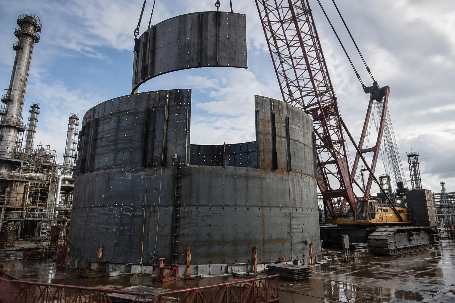
Small units may be shipped with the radiant section assembled, but larger heaters quickly run into the usual industrial reality: transport limits, crane capacity, restricted plot space, field welding, and a schedule that treats every lost shift as a personal insult.
That is why the choice between cylindrical heater ring stacking and panel erection is not a stylistic preference. It is a fabrication and logistics decision that affects the entire radiant section: casing fit-up, coil installation, refractory work, roof assembly, welding access, inspection, and ultimately the heater’s ability to operate with the intended draft and heat-transfer profile.
API 560 provides the governing framework for fired heater design and construction in refining and petrochemical service. It does not hand the project team one universally superior erection method. The practical answer depends on what can be fabricated in the shop, what can be transported, what the site can lift, and how much assembly and welding the field can realistically absorb.
The “best” erection method is usually the one that creates the fewest expensive problems after the first module leaves the truck.
The logistical decision comes before the welding decision
The two methods solve the same broad problem—building a cylindrical radiant section at industrial scale—but they divide the work differently.
With ring stacking, the cylindrical shell is fabricated as a series of horizontal ring sections. These rings are transported to the site, lifted into position, aligned vertically, and welded or connected to the adjacent sections. The result is a shell assembled course by course, with the geometry established around the circumference of each ring.
With panel assembly, the casing is divided into wall panels or larger fabricated sections. These are lifted individually or in groups, positioned around the heater, and joined through vertical or circumferential splices, depending on the design. The method behaves more like assembling a large-sided enclosure than stacking complete cylindrical courses.
Neither approach eliminates field work. It simply changes the type, sequence, and concentration of that work.
The first questions should therefore be brutally practical:
- Can the transport route accept the diameter, length, and weight of the prefabricated sections?
- Is there enough laydown area near the foundation?
- Can the available crane handle the lift radius, not just the nominal module weight?
- Will the field team have safe access to the weld joints at the required elevations?
- Does the design favor shop welding, field welding, or a controlled balance between the two?
- Can coil installation proceed without forcing crews to dismantle access arrangements later?
- Will refractory installation be delayed by shell fit-up, roof work, or inspection hold points?
For a small vertical cylindrical heater, often below 40 MMBtu/hr, the radiant section may be transportable as a single piece. That is the clean version of the story. As the heater grows, the single-piece option usually disappears and the project moves toward prefabricated modules, stacked rings, or spliced panels.
The threshold is not a magic line. Transport dimensions, route restrictions, local lifting capability, and the specific furnace design matter more than a number printed in a procurement summary.
Ring stacking: controlled geometry, repeated lifts
Ring stacking is appealing because it preserves the cylindrical logic of the heater. Each ring arrives as a relatively complete shell section. Once positioned, it can be checked for elevation, roundness, verticality, and alignment before the next ring is added.
That sequence creates a clear construction rhythm:
1. Prepare and verify the foundation, anchor points, and lower support details.
2. Set the floor or lower base components.
3. Lift the first ring section into position and establish its reference geometry.
4. Add successive ring sections, checking fit-up and vertical alignment at each joint.
5. Complete the upper shell, roof, arch, or transition structure.
6. Install the radiant coil and associated supports.
7. Carry out refractory and insulation work after the relevant shell and structural inspections are complete.
The attraction is not that the work becomes easy. It is that the geometry is broken into repeatable stages. A ring section gives the crew a recognizable reference: a continuous circumference rather than a collection of independent wall faces.
That can be particularly useful on large cylindrical furnace shells where maintaining roundness is a central concern. A shell assembled from ring sections tends to make the circumferential relationship visible at every stage. Misalignment is not something that can politely hide behind the next panel.
Where ring stacking creates pressure
The method also concentrates several risks.
A ring must arrive in a condition that makes it worth transporting. If the section is too large or too heavy for the route or crane, the theoretical efficiency of shop fabrication is irrelevant. The project has designed a component that cannot leave the yard without becoming a logistics problem.
Ring lifts can also impose demanding requirements on crane position and site access. The available crane capacity must be considered at the actual working radius, including rigging, wind limitations, obstructions, and the need to place the section accurately rather than merely raise it.
Field welding at horizontal ring joints may be more manageable than a large number of small connections, but it is still field welding. Fit-up tolerances, shell distortion, joint accessibility, inspection, and weather protection all remain live issues. The work may look orderly from the project schedule. It will not feel orderly to the crew if each ring arrives without adequate lifting points, temporary bracing, or clear joint references.
Ring stacking is often a strong option when:
- The heater diameter allows ring sections to be transported economically.
- The site has suitable crane capacity and a reasonable lifting path.
- The project benefits from substantial shop fabrication.
- The design team wants a clear vertical erection sequence.
- The available laydown area can support ring storage and staging.
- The field team can perform the required circumferential fit-up and welding under controlled conditions.
It becomes less attractive when transport dimensions dominate the project or when the site cannot safely stage and rotate large cylindrical sections.
Panel assembly: more pieces, more access questions
Panel assembly divides the casing into wall panels that can be fabricated, transported, and lifted within tighter limits. That is its basic advantage. Instead of moving an entire cylindrical ring, the project moves flatter, narrower components and reconstructs the shell at the site.
The trade-off is obvious enough to be missed in the first design meeting: the easier a panel is to transport, the more connections may need to be made in the field.
A typical panel-based sequence may involve:
1. Setting the floor panels or base elements.
2. Erecting the first wall panels and securing temporary stability.
3. Adding adjacent panels while controlling corner, splice, and circularity relationships.
4. Completing horizontal or vertical splice joints as defined by the design.
5. Installing upper wall panels, roof members, arch components, or the supporting superstructure.
6. Checking shell geometry before coil supports and radiant tubes are permanently installed.
7. Completing refractory work only after the casing and relevant structural details are accepted.
Panel erection can be well suited to sites where transport width and route constraints make full rings impractical. It may also offer more flexibility in fabrication and delivery: panels can be shipped in batches, staged according to the erection sequence, and handled with equipment already available on a congested project site.
But the method shifts complexity into fit-up.
A cylindrical heater is not simply a polygon with enough sides. The casing must achieve the intended shape, support the internal systems, accommodate thermal movement, and work with the refractory and draft design. Every panel splice becomes part of a larger geometric system. A small mismatch at one connection can become an accumulation problem as the erection proceeds around the shell.
The real issue is not the panel. It is the splice
The term “panel assembly” can sound reassuringly modular. Modular is a useful word in a project presentation because it suggests control. On site, it means the joints have to be controlled.
The engineering and construction team must know:
- Which edges are primary fit-up references.
- How panel tolerances are defined and measured.
- Where temporary supports are permitted.
- How the shell is restrained before the roof or upper structure closes the assembly.
- Whether weld sequence can introduce distortion.
- How inspection access will be preserved.
- How internal coil supports and refractory anchors relate to the panel joints.
- Which dimensions must be confirmed before proceeding to the next erection stage.
Panel assembly is not automatically more labor-intensive in every project; the available data does not support a universal labor-hour ranking against ring stacking. It is more accurate to say that the labor profile is different. Ring stacking concentrates work around larger circumferential lifts and joints. Panel assembly may distribute work across more pieces, more alignment points, and more splice locations.
The difference matters because a site can be short of different things. One project is constrained by crane time. Another has excellent lifting capacity but poor access for continuous welding. A third has ample labor but little laydown space. A fourth has a tight commissioning date and no appetite for discovering shell distortion after refractory installation.
There is no prize for choosing the method that looks simpler in a three-dimensional model.
Ring stacking versus panel assembly
The comparison is clearest when the methods are placed against the same project conditions.
| Parameter | Ring stacking | Panel assembly |
|---|---|---|
| Main prefabricated unit | Horizontal cylindrical ring sections | Flat or curved wall panels and related casing sections |
| Transport profile | Larger diameter and often greater width | Narrower individual components, generally easier to route through constrained corridors |
| Field geometry | Circumferential ring-to-ring alignment | Panel-to-panel fit-up, splice control, and cumulative shell geometry |
| Typical lifting pattern | Repeated lifts of complete ring sections | Repeated lifts of individual panels or panel groups |
| Shop fabrication potential | High, provided ring dimensions are transportable | High, especially where smaller shipping units are required |
| Field welding focus | Circumferential joints and associated attachments | Vertical, horizontal, or combined panel splice joints |
| Laydown requirement | Space for ring sections and lifting access | Space for panels, sequencing, and temporary staging |
| Main geometric concern | Roundness, elevation, verticality, ring alignment | Circularity, splice alignment, panel distortion, and cumulative fit-up |
| Access concern | Working around large ring joints and elevated shell courses | Maintaining access to numerous panel splices and internal attachments |
| Best logistical argument | Fewer, larger shell units with a clear stacking sequence | Smaller shipping units for restricted routes, cranes, or plot layouts |
| Main project risk | Oversized transport and demanding ring lifts | Increased splice management and cumulative field fit-up complexity |
The table does not identify a winner because the project itself is the deciding variable. That may sound less satisfying than a universal recommendation. It is also true.
Structural integrity is established during fit-up, not at the end
A fired heater casing is not the pressure boundary in the same sense as the process coil, but it is not decorative cladding either. The radiant section must maintain its intended shape and support the systems that make the heater function: tubes, tube supports, burners, refractory, roof or arch structures, and the transition into the convection section or flue-gas path.
API 560 is the central industry specification for fired heater design and construction. Compliance is not achieved by citing the standard in the design basis and then improvising the erection sequence in the field. The construction method has to preserve the design assumptions.
That means the erection plan should define how the team will control:
- Shell verticality and circularity.
- Floor and base alignment.
- Roof and arch geometry.
- Burner openings and related casing details.
- Tube support locations.
- Expansion and movement allowances.
- Weld sequencing and distortion management.
- Inspection access and acceptance points.
- Interfaces with refractory anchors and lining systems.
The sequence matters because the shell does not exist in isolation. A casing that is technically assembled but geometrically wrong can make later work progressively worse. Coil supports may require adjustment. Refractory thickness may become inconsistent. Burner alignment may be compromised. Access platforms may no longer fit the intended clearances.
This is where the phrase “field fit-up” earns its reputation. It is not a final cosmetic adjustment. It is the point at which shop tolerances, transport handling, lifting deformation, foundation conditions, and actual site geometry meet each other in public.
Shop precision versus field flexibility
Ring stacking generally pushes the project toward larger, more complete shop-fabricated units. Panel assembly can break the casing into smaller units and may offer more flexibility where transportation or lifting limits are restrictive.
But greater shop fabrication is not automatically better if it produces a section that is difficult to transport or impossible to position without excessive temporary work. Likewise, smaller panels are not automatically safer if the field sequence creates too many opportunities for cumulative misalignment.
The useful question is not, “Which method moves more work into the shop?” It is:
Which method puts the most sensitive work in the environment where it can be controlled?
A shop usually offers better protection from weather, more stable fabrication access, repeatable tooling, and easier dimensional control. A site offers unavoidable constraints: changing access, shared cranes, temporary structures, wind, heat, limited work fronts, and coordination with other disciplines.
The design should therefore reserve field work for tasks that genuinely need site assembly. Every additional field splice is a coordination event. Every large module is a transport and lifting event. Both have a price; only the shape of the price changes.
Erection sequence must protect coil installation and refractory work
The casing is only the first half of the radiant section. The heater still has to receive its coil, burner systems, supports, refractory lining, roof or arch assemblies, and connections to the wider fired-heater system.
A poor shell erection sequence creates a predictable chain of delays. The crew cannot install the coil because temporary bracing is still in place. Refractory work begins before all inspection points are closed. Access disappears behind installed components. A splice that was easy to reach from outside becomes awkward once internal items are installed.
The practical sequence should protect the work fronts rather than simply chase the fastest steel erection milestone.
For both ring and panel methods, the sequence generally needs to answer five questions:
1. When is the shell geometrically stable?
Temporary stability is not the same as final stability. The plan should define when the structure can safely accept internal loads, platforms, coil components, and roof assemblies.
2. When can the coil be installed without obstructing casing work?
Coil installation should not be treated as an afterthought squeezed into whatever access remains.
3. When are refractory anchors and lining interfaces verified?
Refractory systems depend on the casing and anchor arrangement being correct. Repairing a geometry problem after lining installation is an expensive way to rediscover the erection sequence.
4. Which inspection points must be closed before concealment?
Once refractory, insulation, platforms, or permanent internals block access, the opportunity for a straightforward inspection is gone.
5. How does the roof or superstructure change lifting access?
Roof trusses and upper structures may provide final stiffness, but they can also eliminate convenient lifting paths for later components.
This is especially relevant for the radiant section because it carries the majority of the heater’s thermal duty. Fired heaters can transfer up to 60% of their total thermal duty through radiation within the radiant firebox. The geometry, tube placement, burner arrangement, refractory condition, and flue-gas movement are therefore operational matters, not merely construction details.
In a radiant section, a few millimetres of construction indifference can become a thermal problem with a much larger personality.
Draft is a construction concern, not only an operating calculation
Natural-draft fired heaters depend on controlled pressure relationships to move combustion air and flue gas through the system. The construction team does not “set” the final draft by good intentions, but the erection and fit-up work can help preserve—or undermine—the geometry and tightness on which the draft system depends.
For natural-draft heaters designed to API 560, a minimum negative draft of 0.10 inches of water column, or 25 Pa, at the arch transition section is maintained to prevent flue-gas leakage. That value is small enough to be underestimated and important enough to punish the project when it is ignored.
The casing, arch transition, roof structure, burner openings, inspection doors, and connected flue-gas path all have to support the intended pressure regime. Field fit-up cannot be reduced to whether the shell closes visually. Openings, gaps, warped joints, or poorly coordinated transition details can affect leakage and flow behavior.
The point is not that ring stacking inherently gives better draft, or that panel assembly inherently gives worse draft. The available facts do not justify such a claim. Draft performance depends on the completed design, the quality of the joints and closures, the flue-gas path, and the commissioning adjustments.
What the erection method changes is how those details are built and verified.
Ring stacking can make the vertical shell sequence straightforward, but each ring joint needs proper closure and inspection. Panel assembly can accommodate restricted transport dimensions, but the greater number of splice interfaces demands disciplined dimensional control and sealing details. In both methods, the transition from radiant section to upper structure deserves particular attention because it is where geometry, draft, and thermal service meet.
Refractory work is where hidden errors become expensive
Refractory lining is often scheduled as if it were the quiet final chapter. It is not. It is a construction system with its own material controls, anchors, surface preparation, installation sequence, curing requirements, and inspection points.
If shell geometry is wrong, refractory thickness may vary. If anchors are misplaced, the lining system may not perform as designed. If the casing is not accepted before lining, later repairs become more disruptive and less visible.
The erection method should therefore be evaluated partly by how well it creates a clean refractory work front. That includes:
- Stable and accepted casing geometry.
- Clear access to all lining areas.
- Verified anchor locations.
- Defined interfaces around burners, tubes, doors, and transitions.
- Minimal need to move heavy equipment through completed lining.
- A curing and protection sequence compatible with the commissioning schedule.
A ring-stacked heater may provide a clear progression from lower shell to upper shell, while a panel-built heater may allow different access arrangements depending on panel size and temporary bracing. Neither advantage exists automatically. The sequence has to be designed rather than assumed.
How to choose without turning the project into a slogan
The method selection should happen early enough to influence the heater design, transport plan, fabrication strategy, and construction schedule. Choosing between ring stacking and panel assembly after the drawings are mature is how projects end up discovering that their preferred module does not fit the road, the crane, or the plot.
A sensible decision process looks at the following conditions together.
Choose ring stacking when the project can support large cylindrical modules
Ring stacking becomes compelling when the route, crane, and laydown plan can comfortably handle the ring dimensions. It is especially useful when the project values a repeated vertical erection sequence and wants to maximize the amount of cylindrical shell fabrication completed in the shop.
That preference should still be checked against:
- Ring weight at the actual crane radius.
- Wind limitations during lifting.
- Storage and staging requirements.
- Access for circumferential fit-up and welding.
- Inspection sequence at each ring joint.
- Interaction with platforms, coil supports, and internal components.
If any of these remain vague, the method is not yet selected. It is merely being discussed.
Choose panel assembly when transport and site access dominate
Panel assembly can be the more practical route when ring dimensions exceed transport limits or when the site has constrained corridors and lifting positions. Smaller components may be easier to deliver and stage, particularly on congested refinery or petrochemical sites where the heater competes for space with existing units, temporary facilities, and other construction packages.
But the project must be ready to manage:
- More individual lifts and component identification.
- Temporary stability during partial assembly.
- Cumulative dimensional control.
- Splice welding and inspection.
- Panel distortion from handling and welding.
- Access to internal attachments and refractory interfaces.
- A clear sequence that prevents the shell from becoming a collection of permanent obstructions.
Panel assembly solves a transport problem by creating a fit-up problem. That can be a very good trade. It is not a free trade.
Use a hybrid strategy when the constraints are mixed
Industrial projects rarely present a single clean constraint. A site may accept some rings but not the complete radiant section. A project may use larger ring sections for the lower shell and panelized details in areas where transport or access changes. The exact arrangement depends on the heater design and fabrication capability, but the principle is simple: do not force the whole heater into one erection philosophy if the project constraints do not behave uniformly.
A hybrid approach can separate the parts that benefit from shop-fabricated cylindrical geometry from the parts that need smaller transport units. It can also align delivery with the actual erection sequence instead of sending every component to site at once and hoping the laydown area develops spontaneously.
That last strategy is popular because it requires no difficult decision. It is also how sites become warehouses.
The field plan should be judged by failure modes
A method comparison becomes useful when it discusses what can go wrong, not only what the brochure claims will go right.
For ring stacking, the main failure modes include:
- A ring exceeds practical transport or lifting limits.
- A ring arrives with distortion that complicates fit-up.
- Crane access changes between planned lifts.
- Circumferential joints are difficult to access or protect.
- Temporary bracing conflicts with later coil or platform installation.
- The sequence advances before roundness and verticality are properly accepted.
For panel assembly, the risks tend to include:
- Panels are delivered out of erection sequence.
- Splice tolerances accumulate around the shell.
- Temporary supports restrict access to later joints.
- Welding sequence distorts the casing.
- Internal attachments are installed before the panel geometry is confirmed.
- Refractory or coil work begins before the shell is fully accepted.
The project should convert these risks into hold points, inspection records, lifting studies, and measurable acceptance criteria. Not because paperwork is a magical industrial solvent, but because memory becomes unreliable once several contractors, shifts, and work fronts are involved.
The erection team needs a shared answer to basic questions: What is the reference elevation? Which axis controls? How is circularity measured? Who accepts the geometry? What happens if the panel or ring is outside tolerance? Which correction methods are allowed, and which ones create a larger problem later?
If those answers are missing, the site will provide its own answers. They will be fast, local, and difficult to audit.
The practical verdict
For vertical cylindrical heaters, ring stacking and panel assembly are both credible erection methods. The right choice depends on the relationship between fabrication, transport, lifting, field welding, plot space, geometry control, and the installation sequence for coils and refractory.
Ring stacking offers a clear cylindrical sequence and substantial shop fabrication when ring dimensions are manageable. Its weaknesses appear when transport routes, crane capacity, or ring handling become the dominant constraints.
Panel assembly offers smaller shipping units and greater adaptability to restricted sites. Its cost is paid through more demanding splice management, temporary stability, and cumulative fit-up control.
API 560 establishes the technical framework, but the standard does not remove the need for project-specific judgment. The radiant section still has to be assembled in the real world, where a crane has a working radius, a weld joint needs access, and a schedule does not care how elegant the three-dimensional model looked.
The decision should be made with the transport plan, lifting study, fabrication drawings, field-welding strategy, coil sequence, refractory work fronts, and draft-related geometry considered as one system.
Do that early, and the erection method becomes a controlled engineering choice. Do it late, and ring stacking versus panel assembly becomes a debate conducted around a module that no longer fits through the gate.